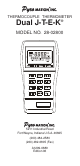
THERMOCOUPLE THERMOMETER Dual J-T-E-K® MODEL NO. 28-02800 5211 Industrial Road Fort Wayne, Indiana U.S.A.
CERTIFICATE OF CONFORMANCE This thermometer was calibrated using equipment traceable to the National Institute of Standards and Technology (NIST). This instrument conforms to NIST monograph 175 revised to ITS-90. The accuracy of the thermometer at the time of calibration was within specifications stated in the operating manual. Model No.
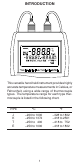
INTRODUCTION This versatile hand-held instrument provides highly accurate temperature measurements in Celsius, or Fahrenheit, using a wide range of thermocouple types. The temperature range for each type thermocouple is listed in the following chart.
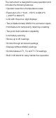
The instrument is designed for easy operation and includes the following features: • Operator selection of temperature scale • Resolution of 0.1° from −150°C to 999.9°C (−238°F to 999.
SAFETY PRECAUTIONS INSTRUMENT IS WARNING THIS DESIGNED TO ACCEPT LOW LEVEL SIGNALS SUPPLIED BY STANDARD THERMOCOUPLES. UNDER NO CIRCUMSTANCES SHOULD THE INPUT VOLTAGE EXCEED THE SPECIFIED 50V RMS. DO NOT USE OR STORE CAUTION THIS INSTRUMENT IN MICROWAVE OVENS OR ANY ABNORMALLY HOT OR COLD AREAS. WEAK BATTERIES SHOULD CAUTION NOT BE LEFT IN THE IN- STRUMENT. DEAD BATTERIES CAN LEAK AND CAUSE DAMAGE TO UNIT. PRESENT AT DANGER VOLTAGES THE THERMOCOUPLES MAY ALSO BE PRESENT AT THE BATTERY TERMINALS.
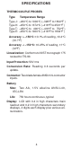
SPECIFICATIONS THERMOCOUPLE PROBES Type Temperature Range Type J: Type K: Type T: Type E: –200°C to 1000°C (–328°F to 1832°F ) –250°C to 1372°C (–418°F to 2501°F ) –250°C to 400°C (–418°F to 752°F ) –250°C to 1000°C (–418°F to 1832°F ) Accuracy > –150°C: ±0.1% of reading, ±0.4°C (±0.7°F) Accuracy < –150°C: ±0.25% of reading, ±1°C (±2°F) Linearization: Conforms to NIST monograph 175 revised to ITS-90. Input Protection: 50V rms Conversion Rate: Reading 0.6 seconds per update.
Temperature/Humidity Range Operating: Stated Accuracy: Useful Range: Storage: Humidity: 18°C to 28°C (64°F to 82°F) 0°C to 40°C (32°F to 104°F) −40°C to 65°C (−40°F to 149°F) 10% to 90% (non-condensing) Dimensions 3 cm D x 8.4 cm W x 15.8 cm H (1.2 in x 3.3 in x 6.2 in) Weight with batteries: 227 grams (8 ounces) Ingress protection: Meets IEC-529 IP-54 for dust and water resistant enclosures.
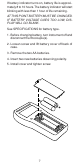
BATTERY INSTALLATION AND REPLACEMENT BATTERIES SHOULD CAUTION WEAK NOT BE LEFT IN THE INSTRUMENT. DEAD BATTERIES CAN LEAK AND CAUSE DAMAGE TO UNIT. VOLTAGES PRESENT AT DANGER THE THERMOCOUPLES MAY ALSO BE PRESENT AT THE BATTERY TERMINALS. ALWAYS DISCONNECT THE THERMOCOUPLE WHEN CHANGING BATTERIES. TO PREVENT IGNITION OF WARNING A HAZARDOUS ATMOS- PHERE, BATTERIES MUST ONLY BE CHANGED IN AN AREA KNOWN TO BE NON-HAZARDOUS.
If battery indicator turns on, battery life is approximately 8 to 10 hours. The battery indicator will start blinking with less than 1 hour of life remaining. AT THIS POINT BATTERY MUST BE CHANGED. IF BATTERY VOLTAGE GOES TOO LOW, DISPLAY WILL GO BLANK. See SPECIFICATIONS for battery type. 1. Before changing battery, turn instrument off and disconnect thermocouple(s). 2. Loosen screw and lift battery cover off back of case. 3. Remove the two AA batteries. 4. Insert two new batteries observing polarity. 5.
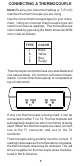
CONNECTING A THERMOCOUPLE Note: Be sure your instrument setting (J, T, E or K) matches the thermocouple you are using. Use the correct thermocouple type for your instrument. Using an incorrect thermocouple type will result in erroneous readings. Thermocouples are color coded by type using the North American ANSI color code as follows: TYPE J K T E COLOR Black Yellow Blue Purple Thermocouple connectors have one wide blade and one narrow blade. Do not force connector in backwards.
9
10
11
QUICK SETUP Note: Review warnings on page 6. 1. Install batteries. 2. Connect thermocouple(s). 3. Press the ON/OFF key. The thermometer performs a self-test and all display digits and indicators, as shown below, should remain on for approximately one second. 4. Use J-T-E-K key to select the correct thermocouple and the °C/°F key to select the desired scale.
COMPLETE SETUP PROCEDURE The setup procedure is used to select the temperature scale, resolution, and thermocouple type. NOTE Selected settings are stored in memory and will remain in memory even after power is turned off, or while batteries are being replaced. SELECTING TEMPERATURE SCALE Select °C or °F by pressing the °C/ °F key. Each time the key is pressed the temperature scale will switch. Switching between °C and °F can be done at any time during operation.
OPERATING PROCEDURES The unit will always power up with the upper display showing T1 unless T1 is not connected. If only T2 is connected at power up, the upper display shows T2 and the lower left display indicates T1 is open. If thermocouples are not connected to T1 or T2 at power up, the upper display indicates an open T1 and the lower right display indicates an open T2.
Dual Probe Measurements The thermometer will automatically determine if one or two thermocouples are connected. When two thermocouples are connected, the upper main display will initially show T1 and the lower right display will show T2. Pressing the T1/T2 key once will cause the upper display to show T2 and the lower left display to show T1. Pressing the T1/T2 key again will cause the upper display to show T1-T2, the lower left display to show T1, and the lower right display to show T2.
Single Probe Measurements The displayed information depends on whether you are using a single probe in the dual probe mode or have changed to the single probe differential mode by pressing the T1/T2 key. If you are using a single probe and in the dual probe mode, momentarily press the MAX s key. The MAX annunciator turns on. If the probe is connected to T1 the maximum reading will be shown in the lower left display.
Dual Probe Measurements Momentarily press the MAX s key. The MAX annunciator turns on, and both maximum T1 and T2 readings appear in the lower display. The T1 reading is on the left display and the T2 reading is on the right display. Press MAX s key again to cancel. Clearing a Maximum Reading Press the CLEAR key then the MAX s key. The maximum memory will be cleared. MINIMUM READINGS The minimum reading function displays the minimum reading since power up or since the last time the clear function was used.
Single Probe Measurements The displayed information depends on whether you are using a single probe in the dual probe mode or have changed to the single probe differential mode by pressing the T1/T2 key. If you are using a single probe and in the dual probe mode, momentarily press the MIN t key. The MIN annunciator turns on. If the probe is connected to T1 the minimum reading will be shown in the lower left display.
DIFFERENTIAL READINGS (T1-T2) The differential function is used to compare two different measurements and display the difference between them. Differential measurements can be made using either one probe or two probes. Single Probe Measurements For single probe measurements, one measurement is stored as the reference measurement, then each following measurement is compared to the reference.
Dual Probe Measurement 1. Connect the two probes to the two points of measurement. The lower left display will indicate the T1 temperature, the lower right display will indicate the T2 temperature. 2. The main display can be scrolled between displaying T1, T2 or the differential temperature T1T2 by repeatedly pressing the T1/T2 key. To display the differential temperature press the T1/T2 key until the T1-T2 annunciator to the right of the main display is on.
1. Momentarily press the STORE key. Both T1 and T2 are stored. The upper main display will momentarily show the storage location number and the STO annunciator will be on. After three seconds the storage number will be replaced with the temperature reading but the STO annunciator remains on to indicate a temperature reading has been stored. The STORE key may be pressed as fast as once per second. 2. Repeat step 1 for all the points to be recorded up to a maximum of 25.
CALIBRATION The calibration function allows both single point and dual point calibration of the thermometer. Single point calibrates the offset only. Dual point calibrates the offset first then calibrates the slope. The thermometer can be calibrated at any temperature. When two probes are used, a match calibration matches the T1 and T2 offsets. It is not necessary to perform a field calibration to obtain specified accuracies.
When calibrating at freezing (0°C or 32°F) it is recommended to use crushed ice made of distilled water in a dewar flask. Add crushed ice to top of flask. Top off flask with distilled water. Continue to add crushed ice to maintain tightly packed crushed ice/water in flask. CALIBRATION PROCEDURES Calibration Procedure (One Probe Detected) This calibration function provides for both an offset and slope field calibration of either T1 or T2.
3. Allow the reading to stabilize. If the displayed temperature is higher or lower than the reference temperature, use the MAX s key to increase the displayed reading or the MIN t key to decrease the displayed reading until the reference temperature is displayed. The MIN t or MAX s key must be pressed at least once. The CAL annunciator should be blinking during this procedure. key to lock the offset cali4. Press the HOLD bration in and advance to the slope calibration.
Calibration Procedure (Two Probes Detected) This calibration function provides for both an offset and slope field calibration of either or both T1 and T2. For proper calibration the following conditions must be observed: • The slope point must be a higher temperature than the offset point. • The difference must be at least 20°C. • Use two points based on the expected high and low temperatures. Temperatures measured outside of these limits may no longer meet accuracy specifications.
5. Allow the reading to stabilize. If the displayed temperature is higher or lower than the reference temperature, use the MAX s key to increase the displayed reading or the MIN t key to decrease the displayed reading until the reference temperature is displayed. The MIN t or MAX s key must be pressed at least once. The CAL annunciator should remain blinking during this procedure. key to lock the T2 offset 6.
11. Press the HOLD key to lock the T2 slope calibration in, or press the CAL key to skip T2 slope calibration. In either case you will now be in T1 = T2 offset calibration. To return to normal operation press any key except CAL key or HOLD key. If either T1 or T2 offset or slope were modified, CAL 1 or 2 will be lit. 12. The MATCH annunciator should be blinking. When both readings (T1 and T2) are stable, press the HOLD key to lock the T1 = T2 offset calibration in. The MATCH annunciator will remain lit. 13.
FIELD CALIBRATION LOCKOUT AND RE-ENABLE The calibration lockout feature, prevents any field calibration changes. The lockout remains in effect until a lockout re-enable has been performed. Use the following procedures to lockout or re-enable the field calibration operation. Lockout Procedure 1. Turn the thermometer off. 2. Simultaneously press and hold the CAL and the CLEAR keys down and momentarily press the ON/OFF key. Continue to hold the CAL and CLEAR keys for at least 5 seconds. Re-Enable Procedure 1.
MAINTENANCE AND TROUBLESHOOTING Properly used, the thermometer should maintain calibration indefinitely and not require service other than occasional cleaning of the housing and changing of the batteries. TO PREVENT IGNITION OF WARNING A HAZARDOUS ATMOSPHERE BY ELECTROSTATIC DISCHARGE, CLEAN WITH DAMP CLOTH. Do not clean with abrasives or solvents. Use mild detergents, never immerse nor use excessive fluid.
SERVICE SUBSTITUTION OF COM- WARNING PONENTS MAY IMPAIR INTRINSIC SAFETY. LA SUBSTITUTION DE AVERTISSEMENT COMPOSANTS PEUT COMPROMETTRE LA SECURITE INTRINSEQUE. There are no internal adjustments or user replaceable parts. If “Err” followed by the numbers 1 through 9 is displayed (see example below) return unit for service. Note that “Err” alone may be displayed during improper field calibration. Note: Serial number label is located inside battery compartment.
TROUBLESHOOTING The following chart lists the most probable faults. There are no internal adjustments or user replaceable parts. If this does not solve the problem refer service to your dealer. FAULT ACTION No display when turned on. Check condition of batteries. Check that batteries are inserted properly. Display shows ---- Out of range indication. Display shows OPEn Open thermocouple connection.
WARRANTY The Manufacturer warrants this product to be free from significant deviations from published specifications. If repair or adjustment is necessary within the warranty period, the problem will be corrected at no charge if it is not due to misuse or abuse on your part as determined by the Manufacturer. Repair costs outside the warranty period, or those resulting from product misuse or abuse, may be invoiced to you. The warranty period for this product is noted on the Warranty Card.