400 ESP Installation Guide ® © 1999 Directed Electronics, Inc.
table of contents What Is Included . . . . . . . . . . . . . . . . . . . . . 3 Installation Points To Remember . . . . . . . . . . 4 Wiring the Control Unit. . . . . . . . . . . . . . . . . 4 Primary Harness (H1), 12-pin Connector . . . . . 5 Primary Harness Wire Connection Guide . . . . . 6 Plug-In LED and Valet/Program Switch . . . . . . 11 Harness 2 (H2), (+/-) Door Lock Outputs . . . 12 Door Lock Wiring Diagrams Type A Door Locks. . . . . Type B Door Locks. . . . . Type C Door Locks . . . . .
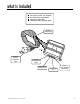
what is included ■ ■ ■ ■ The control module (see diagram) Two 471T remote transmitters The plug-in status LED The plug-in Valet®/Program switch Primary Harness (H1) Pre-wired Failsafe® Starter Kill Relay 3-pin Data/Program Plug H2 Door Lock Harness Port © 1999 Directed Electronics, Inc.
installation points to remember This system has been designed to provide the ultimate in convenience to both the dealer and the end user. The microprocessor at the heart of the system utilizes a sophisticated “Learn Routine” to program transmitters as well as configure operation settings. Transmitter codes and operations settings are stored in “EEPROM” and will remain in memory even if the system’s main power is disconnected for extended periods of time.
primary harness (H1), 12-pin connector H1/1 H1/2 H1/3 H1/4 H1/5 H1/6 H1/7 H1/8 ______ ______ ______ ______ ______ ______ ______ ______ ORANGE WHITE WHITE/BLUE BLACK/WHITE GREEN BLUE (-) 500 mA GROUND-WHEN-ARMED OUTPUT (-) PARKING LIGHT OUTPUT (-) 200 mA CHANNEL 3 VALIDITY OUTPUT (-) 200 mA DOMELIGHT SUPERVISION OUTPUT NO FUNCTION (-) 200 mA SECOND UNLOCK OUTPUT VIOLET NO FUNCTION BLACK (-) CHASSIS GROUND INPUT H1/9 ______ YELLOW (+) SWITCHED IGNITION INPUT H1/10 ______ BROWN (-) HORN HONK OUTPU
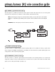
primary harness (H1) wire connection guide H1/1 ORANGE (-) ground-when-armed output This wire supplies a (-) 500 mA ground as long as the system is armed. This output ceases as soon as the system is disarmed. The orange wire is pre-wired to control the DEI® 8618 starter kill relay. NOTE: If connecting the orange wire to control another module, such as a DEI® 529T or 530T window controller, a 1 amp diode (type 1N4004) will be required. Insert the diode as shown in the diagram below.
IMPORTANT! Never use this wire to drive anything but a relay or a low-current input! The transistorized output can only provide 200 mA of current, and connecting directly to a solenoid, motor, or other high-current device will cause it to fail. H1/4 BLACK/WHITE (-) 200 mA domelight supervision output Connect this wire to the optional domelight supervision relay as shown below: IMPORTANT! This output is only intended to drive a relay.
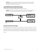
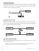
Type A (+) polarity system: Wire relays as shown. Type B (-) polarity system: Connect the BLUE H1/6 wire to the unlock wire in the vehicle and wire the relay as shown. 8 © 1999 Directed Electronics, Inc.
Type C (+) reversing polarity system: Wire relays as shown. H1/8 BLACK (-) chassis ground connection Connect this wire to bare metal, preferably with a factory bolt rather than your own screw (screws tend to either strip or loosen with time). We recommend grounding all your components to the same point in the vehicle. © 1999 Directed Electronics, Inc.
H1/9 YELLOW (+) ignition input Connect this wire to an ignition source. This input must show (+)12V with the key in run position and during cranking. Make sure that this wire cannot be shorted to the chassis at any point. This wire will trigger the system if the ignition is turned on before the unit is disarmed (doors unlocked with the remote). It will also honk the vehicle’s horn and flash the parking lights (if connected).
H1/12 RED/WHITE channel 2, 200mA (-) output When the system receives the transmitter code controlling Channel 2 for longer than 1.5 seconds, the red/white wire will supply an output as long as the transmission continues. This is often used to operate a trunk/hatch release or other relay-driven functions. IMPORTANT! Never use this wire to drive anything but a relay or a low-current input! The transistorized output can only supply 200 mA of current.
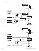
harness 2 (H2), (+/-) door lock outputs H2/A H2/B H2/C ______ ______ ______ GREEN (-) LOCK, (+) UNLOCK OUTPUT EMPTY UNLESS USING 451M BLUE (-) UNLOCK, (+) LOCK OUTPUT door lock wiring diagrams This system can control two common power door lock types without any additional parts! To interface with some vehicles or if an actuator is to be installed, you will need a 451M Door Lock Relay Satellite or two relays.
IMPORTANT! Remember that the functions of these wires reverse between Type A and Type B! type B: (-) pulses from the switch to the factory relays This system is common in many Toyotas, Nissans, Hondas and Saturns, as well as Fords with the keyless-entry systems (some other Fords also use Type B). The switch will have three wires on it, and one wire will test ground all the time. One wire will pulse (-) when the switch locks the doors, and the other wire will pulse (-) when the switch unlocks the doors.
type C: reversing polarity Interfacing with a reversing polarity system requires either two relays or one 451M (not included). It is critical to identify the proper wires and locate the master switch to interface properly. Locate wires that show voltage on lock and unlock. Cut one of the suspect wires and check operation of the locks from both switches. If one switch loses operation in both directions and the other switch operates in one direction only, you have located one of the target wires.
type D: after-market actuators In order for this system to control one or more aftermarket actuators, a 451M or two relays (optional) are needed. Vehicles without factory power door locks require the installation of one actuator per door. This requires mounting the door lock actuator inside the door. Other vehicles may only require one actuator installed in the driver's door if all door locks are operated when the driver's lock is used.
type E: mercedes-benz and audi (1985 & newer) Door locks are controlled by an electrically activated vacuum pump. Some Mercedes and Audis use a Type D system. Test by locking doors from the passenger key cylinder. If all the doors lock, the vehicle's door lock system can be controlled with just two relays (optional). The control wire can be found in either kick panel and will show (+)12V when doors are unlocked and (-) ground when doors are locked. To interface see diagram below.
™ transmitter/receiver learn routine Transmitters are taught to the system using the Learn Routine. This system will learn up to four transmitters. Both transmitters come factory programmed using Button I for lock, unlock, and panic; Button II for Channel 2 and Silent Mode; and Buttons I and II together operate Channel 3. This configuration can be changed or new remotes can be added to the system using the Learn Routine.
to advance from one channel to another You can advance from one channel to another by releasing the Valet®/Program switch and tapping it to advance channels and then holding it. For instance: You have programmed Channel 1 and you want to program Channel 2. Release the Valet®/Program switch. Press it one time and release it to advance from Channel 1 to Channel 2. Now, press and hold the Valet/Program switch down and the unit will chirp twice. As before, do not release it.
oem style configuration A remote that uses the OEM Style Configuration operates similarly to many factory keyless entry remotes. An OEM Style Configuration transmitter allows arming and disarming with separate buttons. When programmed for OEM Style Configuration, the transmitter buttons are assigned to the following functions: Button I ...........................operates.........................Arm/Panic Button II ..........................operates.........................
™ operating settings learn routine Many of the operating settings of this unit are programmable. They can be changed whenever necessary through a computer-based learn routine. To simplify programming, the DEI Bitwriter (P/N 998T) can be used to change options as well as lock the Learn Routine. If there is no response from the Learn Routine, plug the DEI Bitwriter into the data port and verify that the Feature Programming is unlocked. 1. Key. Turn the ignition on and then back off.
to access another feature You can advance from feature to feature by pressing and releasing the Valet®/Program switch the number of times necessary to get from the feature you just programmed to the feature you wish to access. For example, if you just programmed Feature 1 for passive arming and you want to program Feature 2 (Arm/Disarm Confirmation Honks): 1. Release the Valet®/Program switch. 2. Press and release the Valet/Program switch once to advance from Feature 1 to Feature 2. 3.
feature descriptions 1 ACTIVE/PASSIVE ARMING: When active arming is selected, the system will only arm when the transmitter is used. When set to passive, the system will arm automatically 30 seconds after the ignition is turned off. Passive arming is indicated by the rapid flashing of the LED. 2 ARM/DISARM CONFIRMATION HONKS ON/OFF: This feature controls the horn honks that confirm the arming and disarming of the system.
Disabling the Code Hopping™ feature lets the receiver ignore the Code Hopping™ part of the transmitted word. As a result, the unit may have better range with Code Hopping™ off. rapid resume logic This DEI system will store its current state to non-volatile memory. If power is lost and then reconnected the system will recall the stored state from memory.
troubleshooting Starter kill does not work: ■ Is the correct starter wire being interrupted? If the car starts when the starter kill relay is completely disconnected, the wrong starter wire has been cut and interrupted. ■ Is the yellow wire connected to “true” ignition? Make sure this wire is connected to a wire that has power in the run and start positions. The Valet® switch does not work. ■ Is it plugged into the correct socket? See Plug-In LED and Valet®/Program Switch section.