Q Simplify SANblade 2300 Series User’s Guide 2-Gb Fibre Channel to cPCI and SBus Host Bus Adapters CF2351102-00 F Page i
Q SANblade 2300 Series User’s Guide 2-Gb Fibre Channel to cPCI and SBus Host Bus Adapters Information furnished in this manual is believed to be accurate and reliable. However, QLogic Corporation assumes no responsibility for its use, nor for any infringements of patents or other rights of third parties which may result from its use. QLogic Corporation reserves the right to change product specifications at any time without notice.
Table of Contents Section 1 Introduction 1.1 1.2 1.3 1.4 How to Use this Guide . . . . . . . . . . . . . . . . . . . . . . . . . . . . . . . . . . . . . . . General Description . . . . . . . . . . . . . . . . . . . . . . . . . . . . . . . . . . . . . . . . . What is Fibre Channel? . . . . . . . . . . . . . . . . . . . . . . . . . . . . . . . . . . . . . . Features . . . . . . . . . . . . . . . . . . . . . . . . . . . . . . . . . . . . . . . . . . . . . . . . . .
SANblade 2300 User’s Guide 2-Gb Fibre Channel to cPCI and SBus Host Bus Adapters Q 3.3 3.4 3.4.1 3.4.2 3.4.3 3.4.4 3.4.5 3.4.6 3.5 3.6 3.7 3.7.1 3.7.2 Removing the QCP2340/2342 HBA . . . . . . . . . . . . . . . . . . . . . . . . . . . . . FCode . . . . . . . . . . . . . . . . . . . . . . . . . . . . . . . . . . . . . . . . . . . . . . . . . . . . Updating FCode on the QCP2340/2342 HBA . . . . . . . . . . . . . . . . . . . Setting the QCP2340/2342 HBA Connection Mode . . . . . . . . . . . . . .
Q SANblade 2300 User’s Guide 2-Gb Fibre Channel to cPCI and SBus Host Bus Adapters Part II Software Section 6 Solaris SPARC Driver Installation 6.1 6.2 6.3 6.4 6.5 Introduction . . . . . . . . . . . . . . . . . . . . . . . . . . . . . . . . . . . . . . . . . . . . . . . . Pre-installation Requirements. . . . . . . . . . . . . . . . . . . . . . . . . . . . . . . . . . Installing the Solaris SPARC Driver from a CD-ROM. . . . . . . . . . . . . . . .
SANblade 2300 User’s Guide 2-Gb Fibre Channel to cPCI and SBus Host Bus Adapters Q Notes Page vi CF2351102-00 F
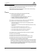
Section 1 Introduction 1.1 How to Use this Guide The SANblade QLogic host bus adapters (HBAs) supported in this document are described in the following paragraphs. They are collectively referred to as the QCP/QSB23xx HBA unless otherwise noted. The QCP23xx HBAs are all 64-bit PCI to Fibre Channel optical media. The QSB23xx HBAs are all 64-bit SBus to Fibre Channel optical media.
Q 1 – Introduction Features interface for intermediate distances (less than 500 meters at the data rate of 1 Gbps; less than 300 meters at the data rate of 2 Gbps). With increased connectivity and performance, Fibre Channel is the technology preferred and used by system designers. 1.4 Features ■ Compliance with the following PCI standards (QCP HBAs): ❑ ❑ ❑ ❑ ❑ PCI Local Bus Specification, revision 2.1 PCI Hot Plug Specification, revision 1.0 PCI Power Management Interface Specification, revision 1.
Part I Hardware This part of the SANblade 2300 User’s Guide describes the host bus adapters (HBAs) and how to install and configure them. See the section that corresponds to your HBA. Section 5 contains troubleshooting information.
Q I – Hardware Notes I-2 CF2351102-00 F
Section 2 QCP2330/2332 2.1 QCP2330/2332 HBA Components Figure 2-1 identifies the QCP2330/2332 HBA components referenced throughout this section. Each QCP2330/2332 HBA has a unique serial number, located on the back of the HBA. Take a minute to write down the serial number of the QCP2330/2332 HBA in the unlikely event that the NVRAM is corrupted. 1 J1 3 ISP CHIP J5 and J1 QCP2332 ONLY J5 QCP2332 ONLY J6 ISP CHIP 1 J2 3 LED1 RELEASE SWITCH NOTE: THE SERIAL NUMBER IS ON THE OTHER SIDE OF THE HBA.
Q 2 – QCP2330/2332 Installation and Removal 2.1.2 Jumpers Jumpers J1 (QCP2332) and J2 on the QCP2330/2332 HBA determine the default state of connectors J5 (QCP2332) and J6, respectively. The jumpers are set at the factory with a jumper plug on pins 2–3, which enables the connectors. CAUTION! Changing the jumper settings can result in the HBA being inoperable. 2.
Q 2 – QCP2330/2332 Installation and Removal 2.2.2 Installation in the Computer (Hot Swap) Perform the following steps to install the QCP2330/2332 HBA without shutting down the system (hot swap). See section 2.2.1 for standard installation instructions. 1. Log on to the system as a superuser. 2. At the prompt (#), type the following command to find an available slot for the QCP2330/2332 HBA: cfgadm A list of the system’s processors, memory, and I/O boats appears, as in the following example.
Q 2 – QCP2330/2332 Installation and Removal 4. Type the cfgadm command (see step 2) to verify that the system recognizes the QCP2330/2332 HBA and that the HBA is not configured. In the following example, the QCP2330/2332 HBA has been installed in slot 4 and is not configured. Ap_Id Type Receptacle Occupant Condition N0.IB6 cPCI_I/O_bo connected configured ok N0.IB8 unknown empty unconfigured unknown N0.SB0 CPU_Board connected configured ok N0.
Q 2 – QCP2330/2332 FCode 6. Connect the appropriate cables from the devices to the J5 (QCP2332) and J6 connectors. 7. Check the QCP2330/2332 HBA hot swap LED1; it should be off, indicating that the HBA is active. See section 6 for detailed instructions on how to install the software driver. If you need FCode, see section 2.4 for instructions on how to install or update the FCode on the QCP2330/2332 HBA. 2.3 Removing the QCP2330/2332 HBA Follow these steps to unconfigure and remove the QCP2330/2332 HBA.
Q 2 – QCP2330/2332 FCode 3. Set the QCP2330/2332 HBA loop ID (see section 2.4.3). 4. Select the boot device (see section 2.4.4). 5. Build the bootable disk (see section 2.4.5). 2.4.1 Updating FCode on the QCP2330/2332 HBA If you need to update the FCode on the QCP2330/2332 HBA, use the QLogic qla2x00 flash utility. A QLogic Solaris SPARC driver revision 3.06 or later must be installed before the flash utility can be run.
Q 2 – QCP2330/2332 FCode The new connection mode displays. For example: Calculating NVRAM checksum, please wait... Current HBA connection mode: 0 - Loop Only Possible connection mode choices: 0 - Loop Only 1 - Point-to-point only 2 - Loop preferred, otherwise point-to-point 2.4.3 Setting the QCP2330/2332 HBA Loop ID When the QCP2330/2332 HBA is currently operating in loop mode (through connection mode 0 or connection mode 2), perform the following steps to view its loop ID and change it if necessary: 1.
Q 2 – QCP2330/2332 FCode 2. Select the QCP2330/2332 HBA attached to the Fibre Channel device from which you want to boot. For example, type the following at the ok prompt: ok " /pci@1f,0/pci@1/QLGC,qla@4" select-dev 3. Use the show-children command to view the devices attached to the QCP2330/2332 HBA. For example: ok show-children 4. The list of devices displays. Write down the boot device’s world wide name (WWN), loop ID, and logical unit number (LUN). 5.
Q 2 – QCP2330/2332 FCode To build a bootable disk, perform the following steps: 1. Determine the amount of disk space used/available on your current boot disk. Use the df command for a listing.
Q 2 – QCP2330/2332 FCode d. At the partition prompt, type print. The partition table displays, as in the following example. Part 0 1 2 3 4 5 6 7 Tag root swap backup unassigned unassigned unassigned unassigned unassigned Flag wm wu wu wm wm wm wm wm Cylinders 0 - 8738 8739 - 9188 0 - 9201 0 0 0 0 0 Size 4.00GB 210.94MB 4.21GB 0 0 0 0 0 Blocks (8739/0/0) 8389440 (450/0/0) 432000 (9202/0/0) 8833920 (0/0/0) 0 (0/0/0) 0 (0/0/0) 0 (0/0/0) 0 (0/0/0) 0 e. At the partition prompt, type label.
Q 2 – QCP2330/2332 FCode 10. Shut down the system. Type the following: /sbin/init 0 11. Boot from the newly created boot disk. For example: boot /pci@1f,0/pci@1/QLGC,qla@4/sd@82,0 NOTE: The target device ID (sd@82) is in hexadecimal. The decimal value is used in step 3. 12. View the current dump device setting. For example: # dumpadm Dump content: kernel pages Dump device: /dev/dsk/c0t0d0s1 (swap) Savecore directory: /var/crash/saturn Savecore enabled: yes 13.
Q 2 – QCP2330/2332 Specifications Table 2-1 lists the values to enter and their corresponding data rates. Table 2-1. Fibre Channel Data Rates Value Data Rate 0 One gigabit 1 Two gigabits 2 Auto-negotiated rate 2.5 Specifications Tables 2-2 and 2-3 define the QCP2330/2332 specifications. Table 2-2.
Q 2 – QCP2330/2332 Agency Certification 2.6 Label The transceiver on the QCP2330/2332 HBA is a Class I laser product. It complies with IEC 825-1 and FDA 21 CFR 1040.10 and 1040.11. The transceiver must be operated under recommended operating conditions. CLASS I LASER PRODUCT 2.7 Agency Certification The following sections contain a summary of EMC/EMI test specifications performed on the QCP2330/2332 (CF2310401) to comply with emission, immunity and product safety standards. 2.7.
Q 2 – QCP2330/2332 Agency Certification ❑ EN61000-3-2:1995 Harmonic Current Emission ❑ EN61000-3-3:1994 Voltage Fluctuation and Flicker ■ VCCI, Class A ■ AS/NZS 3548, Class AC-tick 2.7.2 Product Safety Requirements ■ UL, cUL ❑ ❑ ❑ ■ 73/23/EEC Low Voltage Directive ❑ ❑ 2-14 UL 6095050 CSA C22.
Section 3 QCP2340/2342 3.1 QCP2340/2342 HBA Components Figure 3-1 identifies the QCP2340/2342 HBA components referenced throughout this section. Each QCP2340/2342 HBA has a unique serial number, located on the back of the HBA. Take a minute to write down the serial number of the QCP2340/2342 HBA in the unlikely event that the NVRAM is corrupted.
Q 3 – QCP2340/2342 Installation and Removal 3.1.1 LEDs The QCP2340/2342 LED1 and LED2 (QCP2342) function as shown in table 3-1. Table 3-1. LED1 and LED2 (QCP2342) Activity Green LED Amber LED Activity On On Power On Off Online Off On Signal acquired Off Flashing Loss of synchronization Flashing Flashing Firmware error In a standard installation, LED3 is off, indicating that the HBA is active. In a hot swap installation, LED3 turns blue while the HBA is inserted.
Q 3 – QCP2340/2342 Installation and Removal 3. Place the QCP2340/2342 HBA into the slot. Carefully press the HBA into the slot until it seats firmly (the switch clicks into a locked position when the HBA is seated). 4. Connect the appropriate cables from the devices to the J2 (QCP2342) and J1 connectors. 5. Power up all external FC devices, then power up the system and observe the monitor.
Q 3 – QCP2340/2342 Installation and Removal A list of the system’s processors, memory, and I/O boats appears, as in the following example. In this example, cPCI slots 0, 1, 3, and 4 are available. Ap_Id Type Receptacle Occupant Condition N0.IB6 cPCI_I/O_bo connected configured ok N0.IB8 unknown empty unconfigured unknown N0.SB0 CPU_Board connected configured ok N0.
Q 3 – QCP2340/2342 Installation and Removal 4. Type the cfgadm command (see step 2) to verify that the system recognizes the QCP2340/2342 HBA and that the HBA is not configured. In the following example, the QCP2340/2342 HBA has been installed in slot 4 and is not configured. Ap_Id Type Receptacle Occupant Condition N0.IB6 cPCI_I/O_bo connected configured ok N0.IB8 unknown empty unconfigured unknown N0.SB0 CPU_Board connected configured ok N0.
Q 3 – QCP2340/2342 Removing the QCP2340/2342 HBA 6. Connect the appropriate cables from the devices to the J2 (QCP2342) and J1 connectors. 7. Check the QCP2340/2342 HBA hot swap LED3; it should be off, indicating that the HBA is active. See section 6 for detailed instructions on how to install the software driver. If you need FCode, see section 3.4 for instructions on how to install or update the FCode on the QCP2340/2342 HBA. 3.
Q 3 – QCP2340/2342 FCode 3. Set the QCP2340/2342 HBA loop ID (see section 3.4.3). 4. Select the boot device (see section 3.4.4). 5. Build the bootable disk (see section 3.4.5). The QCP2340 has one channel; the QCP2342 has two channels. The code distinguishes between the channels as follows: ■ ■ qla@4 (QCP2340 and QCP2342 (first channel)) qla@4,1 (QCP2342 second channel) Throughout the FCode sections, the examples use qla@4;substitute qla@4,1 for the example to apply to the QCP2342’s second channel. 3.4.
Q 3 – QCP2340/2342 FCode The connection mode and options display. For example: Current HBA connection mode: 2 - Point-to-point only Possible connection mode choices: 0 - Loop Only 1 - Point-to-point only 2 - Loop preferred, otherwise point-to-point 2. If the connection mode is not correct based on the devices connected to the QCP2340/2342 HBA, change it using the set-connection-mode command. For example: ok 0 set-connection-mode The new connection mode displays.
Q 3 – QCP2340/2342 FCode 3.4.4 Selecting the Boot Device Perform the following steps to select a Fibre Channel device that is attached to the QCP2340/2342 HBA as the boot device: 1. Use the show-devs command to display the device tree for all devices attached to the machine. ok show-devs The device tree displays. The QCP2340/2342 HBAs with FCode are referenced with QLGC,qla@. For example: ok show-devs . .
Q 3 – QCP2340/2342 FCode 3.4.5 Building the Bootable Disk This procedure assumes that the system is already booted from an existing system hard disk, and that you have already performed a full system backup. The device path on each system differs, depending on the PCI bus slot, target ID, LUN, etc. The device name shown in this example is for a device on the third PCI bus slot, target ID 130, LUN 0, slice 0.
Q 3 – QCP2340/2342 FCode a. At the root prompt, type format. b. A list of available hard disks displays. Specify the disk. c. At the format prompt, type partition. d. At the partition prompt, type print. The partition table displays, as in the following example. Part 0 1 2 3 4 5 6 7 Tag root swap backup unassigned unassigned unassigned unassigned unassigned Flag wm wu wu wm wm wm wm wm Cylinders 0 - 8738 8739 - 9188 0 - 9201 0 0 0 0 0 Size 4.00GB 210.94MB 4.
Q 3 – QCP2340/2342 FCode 9. Edit the new vfstab file to properly mount the new partitions during boot. In this case, each reference to c0t0d0s0 is changed to c3t130d0s0. For example: vi /mnt/etc/vfstab 10. Shut down the system. Type the following: /sbin/init 0 11. Boot from the newly created boot disk. For example: boot /pci@1f,0/pci@1/QLGC,qla@4/sd@82,0 NOTE: The target device ID (sd@82) is in hexadecimal. The decimal value is used in step 3. 12. View the current dump device setting.
Q 3 – QCP2340/2342 Specifications 3.4.6 Setting and Viewing the Fibre Channel Data Rate Use the show-data-rate command to view the current QCP2340/2342 Fibre Channel data rate. For example: ok show-data-rate Current HBA data rate: One Gigabit rate Use the set-data-rate command to change the current QCP2340/2342 Fibre Channel data rate. For example: ok 1 set-data-rate Calculating NVRAM checksum, please wait...
Q 3 – QCP2340/2342 Label Table 3-4. QCP2340/2342 Board Specifications (Continued) Type Specification RAM 256K bytes of synchronous SRAM (SSRAM) per RISC NVRAM 256 bytes, field programmable Flash 512K bytes of flash ROM, field programmable On-board DMA Three independent DMA channels: two data and one command. Integrated frame buffer FIFOs (6K-byte receive and 4K-byte transmit) for each data channel.
Q 3 – QCP2340/2342 Agency Certification ❑ EN55022:1995 ❑ ❑ ❑ Class A Radiated Emission Conducted Emission Class A Class A EN55024:1998 ❑ ❑ ❑ ❑ ❑ ❑ ❑ ❑ Immunity Standards EN61000-4-2 :1995 EN61000-4-3 :1995 EN61000-4-4 :1995 EN61000-4-5 :1995 EN61000-4-6 :1996 EN61000-4-8 : 1994 EN61000-4-11: 1994 ESD RF Electro Magnetic Field Fast Transient/Burst Fast Surge Common/Differential RF Conducted Susceptibility Power Frequency Magnetic Filed Voltage Dips and Interrupt ❑ EN61000-3-2:1995 Harmonic Curre
3 – QCP2340/2342 Agency Certification Q Notes 3-16 CF2351102-00 F
Section 4 QSB2340/2342 4.1 QSB2340/2342 HBA Components Figure 4-1 identifies the QSB2340/2342 HBA components referenced throughout this section. LED2 PORT 2 J10 PORT 1 LED1 PORT 1 J9 PORT 2 1 J10, J7, LED2 QSB2342 ONLY ISP CHIP SERIAL NUMBER J7 3 J8 Each QSB2340/2342 HBA has a unique serial number, located on the back of the HBA. Take a minute to write down the serial number of the QSB2340/2342 HBA in the unlikely event that the NVRAM is corrupted. J1 NOTE: The QLOGIC FPGA is on the back.
Q 4 – QSB2340/2342 Installation in the Computer 4.1.1 LEDs The QSB2340/2342 LED1 and LED2 (QSB2342) function as shown in table 4-1. Table 4-1. LED1 and LED2 (QCP2342) Activity Green LED Amber LED Activity On On Power On Off Online Off On Signal acquired Off Flashing Loss of synchronization Flashing Flashing Firmware error 4.1.2 Jumpers Jumpers J7 (QSB2342) and J8 on the QSB2340/2342 HBA determine the default state of connectors J10 (QSB2342) and J9, respectively.
Q 4 – QSB2340/2342 FCode See section 6 for detailed instructions on how to install the software driver. If you need FCode, see section 4.3 for instructions on how to install or update the FCode on the QSB2340/2342 HBA. 4.3 FCode This section provides instructions for installing FCode on a QSB2340/2342 HBA installed in a Solaris SPARC system. A QSB2340/2342 HBA with FCode loaded in its flash ROM provides boot capability to its attached devices. The following files are included.
Q 4 – QSB2340/2342 FCode 4.3.2 Setting the QSB2340/2342 HBA Connection Mode Perform the following steps to view the current QSB2340/2342 HBA connection mode and change it if necessary: 1. Perform steps 1 and 2 in section 4.3.4. 2. To view the current connection mode, type the show-connection-mode command. ok show-connection-mode The connection mode and options display.
Q 4 – QSB2340/2342 FCode 3. If the loop ID is not correct, change it using the set-adapter-loopid command. For example: ok 0 set-adapter-loopid The new loop ID displays. For example: Adapter loopid - 0 4.3.4 Selecting the Boot Device Perform the following steps to select a Fibre Channel device that is attached to the QSB2340/2342 HBA as the boot device. 1. Use the show-devs command to display the device tree for all devices attached to the machine. ok show-devs The device tree displays.
Q 4 – QSB2340/2342 FCode 5. Save the boot device information to the QSB2340/2342 HBA’s NVRAM. Use the set-boot-id command. Include the selected QSB2340/2342 HBA’s WWN, loop ID, and LUN. For example: ok 2200002037009eeb 82 0 set-boot-id The following displays: Calculating NVRAM checksum, please wait.... done Boot device login successful Boot WWN - 20000020 37009eeb WWPN - 22000020 37009eeb Id - 82 Lun - 0 ok To boot the QSB2340/2342 HBA, type the complete boot path, including the loop ID and LUN.
Q 4 – QSB2340/2342 FCode To build a bootable disk, perform the following steps: 1. Determine the amount of disk space used/available on your current boot disk. Use the df command for a listing.
Q 4 – QSB2340/2342 FCode a. At the root prompt, type format. b. A list of available hard disks displays. Specify the disk. c. At the format prompt, type partition. d. At the partition prompt, type print. The partition table displays, as in the following example. Part 0 1 2 3 4 5 6 7 Tag root swap backup unassigned unassigned unassigned unassigned unassigned Flag wm wu wu wm wm wm wm wm Cylinders 0 - 8738 8739 - 9188 0 - 9201 0 0 0 0 0 Size 4.00GB 210.94MB 4.
Q 4 – QSB2340/2342 Specifications 9. Edit the new vfstab file to properly mount the new partitions during boot. In this case, each reference to c0t0d0s0 is changed to c3t130d0s0. For example: vi /mnt/etc/vfstab 10. Shutdown the system. Type the following: /sbin/init 0 11. Boot from the newly created boot disk. For example: boot /sbus@1f,0/QLGC,qla@1,30000/sd@82,0 NOTE: The target device ID (sd@82) is in hexadecimal. The decimal value is used in step 3. 4.
Q 4 – QSB2340/2342 Label Table 4-3. QSB2340/2342 Board Specifications (Continued) Type Specification Form factor 14.7cm×8.4cm (5.8"×8.4") Operating power Less than 15 watts 4.5 Label The transceiver on the QSB2340/2342 HBA is a Class I laser product. It complies with IEC 825-1 and FDA 21 CFR 1040.10 and 1040.11. The transceiver must be operated under recommended operating conditions. CLASS I LASER PRODUCT 4.
Q 4 – QSB2340/2342 Agency Certification ❑ ❑ ❑ ❑ EN61000-4-5 :1995 EN61000-4-6 :1996 EN61000-4-8 : 1993 EN61000-4-11: 1994 Fast Surge Common/Differential RF Conducted Susceptibility Power Frequency Magnetic Filed Voltage Dips and Interrupt ❑ EN61000-3-2:1995 Harmonic Current Emission ❑ EN61000-3-3:1995 Voltage Fluctuation and Flicker ■ VCCI, Class B ■ AS/NZS 3548 Class B 4.6.2 Product Safety Requirements ■ UL, cUL ❑ ❑ ❑ CF2351102-00 F UL60950 CSA C22.
4 – QSB2340/2342 Agency Certification Q Notes 4-12 CF2351102-00 F
Section 5 Troubleshooting 5.1 Problems After Installation There are two basic types of installation problems that can cause your QCP/QSB23xx HBA to function incorrectly: hardware problems and Fibre Channel problems. The following section provides itemized checklists to help you determine why your QCP/QSB23xx HBA is not functioning. 5.
5 – Troubleshooting Fibre Channel Problem Checklist Q Notes 5-2 CF2351102-00 F
Part II Software This part of the SANblade 2300 User’s Guide describes how to install the software drivers for the supported operating systems. See the section that corresponds to your computer’s operating system: Operating System Solaris SPARC Section 6 Before you install the software drivers, you need to locate and download the appropriate drivers for your operating system. The latest version of the QLA23xx drivers are located on the QLogic Web site, www.qlogic.com.
Q II – Software Notes II-2 CF2351102-00 F
Section 6 Solaris SPARC Driver Installation (QL2300) 6.1 Introduction This section provides instructions for installing the Solaris SPARC driver in an already installed Solaris SPARC operating system. The naming convention for the drivers, associated files, and messages is QLA; however, the Solaris SPARC driver supports standard QLogic PCI HBAs (QLAxxxx), cPCI HBAs (QCPxxxx), and SBus HBAs (QSBxxxx). The latest version of the Solaris SPARC driver package is available on the QLogic web site (www.qlogic.
Q 6 – Solaris SPARC Driver Installation Installing the Solaris SPARC Driver from a CD-ROM qla2300 driver versions 4.11 (and earlier) have the following package names: ❑ ❑ ❑ QLA2300-1 (Solaris 2.6) QLA2300-2 (Solaris 2.7) QLA2300-3 (Solaris 2.8 and 9) Checks within the package installation will terminate the new driver installation if a pervious version of the driver package is found. For additional information, please review the latest Solaris README.TXT file, available on the QLogic web site (www.
Q 6 – Solaris SPARC Driver Installation Installing the Solaris SPARC Driver from the QLogic Web Site 1. Log on to the system as a superuser. 2. Download the driver package from the QLogic Web site (www.qlogic.com) to a directory on the Solaris machine’s hard disk. 3. At the command prompt, change the directory (cd) to the directory where the file was downloaded. 4. At the command prompt, type: uncompress ./qla2300_pkg.Z 5. Step 4 produces a file in the same directory called qla2300_pkg. 6.
Q 6 – Solaris SPARC Driver Installation Installing the Solaris SPARC Driver from the QLogic Web Site 9. You are prompted to select the directory where the driver will be installed. For example: Processing package instance from QLogic QLA2300 driver (sparc) Solaris, Rev=X.XX Copyright (c) 1996-2003, by QLogic Corporation. All rights reserved. Where do you want the driver object installed (default=/kernel/drv): 10. Press ENTER to accept the default. 11.
Q 6 – Solaris SPARC Driver Installation FCode 13. The pkgadd program then installs the SDM library, if selected in step 8. A script warning is posted, asking whether to continue the installation. For example: Processing package instance from QLogic SDM Library (sparc) Solaris 7-8-9, Rev=X.XX Copyright (c) 2003, by QLogic Corporation. All rights reserved. ## ## ## ## ## Processing package information. Processing system information. Verifying disk space requirements.
6 – Solaris SPARC Driver Installation FCode Q Notes 6-6 CF2351102-00 F