
User's Manual

4 – Hardware Installation
Switch Configuration and Monitoring
IB0056101-00 G 4-17
A
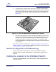
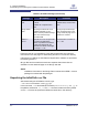
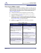
8. Insert the card by pressing firmly and evenly on the top of the horizontal
bracket and the top rear corner of the card simultaneously. The card should
insert evenly into the slot. Be careful not to push, grab, or put pressure on
any other part of the card, and avoid touching any of the components. See
Figure 4-10.
Figure 4-10. QHT7140 Without Riser Installed in a 3U Chassis
9. Secure the face plate to the chassis. The QLogic adapter has a screw hole
on the side of the face plate that can be attached to the chassis with a
retention screw. The securing method may vary depending on the chassis
manufacturer. Refer to the system documentation for information about
mounting details such as mounting holes, and screws to secure the card, or
other brackets.
Next, install the cables, as described in “Cabling the Adapter to the InfiniBand
Switch” on page 4-17. Then test your installation by powering up the system (see
“Completing the Installation” on page 4-18).
Switch Configuration and Monitoring
The QLogic interconnect is designed to work with all InfiniBand-compliant
switches. Follow the vendor documentation for installing and configuring your
switches.
Cabling the Adapter to the InfiniBand Switch
Follow the recommendations of your cable vendor for cable management and
proper bend radius.