
Technical Manual


72 73
NO C
1
NO C
2
1 2 3 4 5 6 7 8
A B
CNTRL
12V
ALARM IN
This DVR features connections for external alarms – both input and output. When an event is
detected the system can notify local users or send notification to a monitoring service. At the
same time, the system can accept signals from motion detectors, smoke detectors or other
alarms and begin recording based on that input and your settings.
You will need to have the manual for your alarm(s) handy to ensure the proper settings within
the DVR.
ALARMS
CHAPTER 6
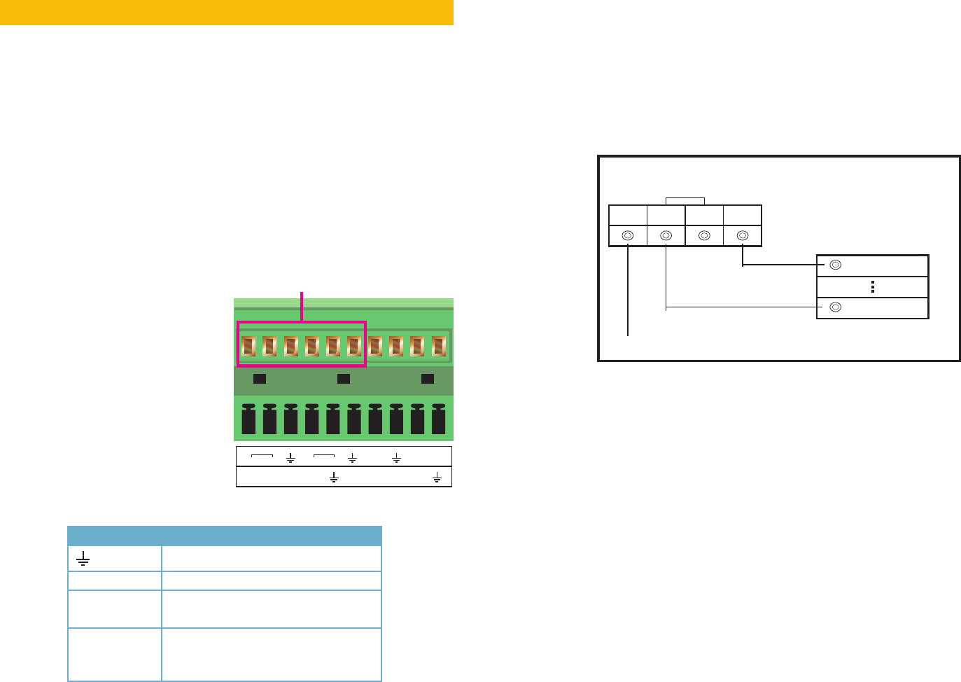
6.1 ALARM INPUT
When attaching alarms, the following criteria
must be met:
1. The alarm input must be grounded.
2. A grounding signal is required for the
alarm input
3. When connecting the DVR to another
device - including another DVR - through
the alarm input, a relay should be used to
separate them.
Parameter Grounding Alarm
Ground line
Alarm Input 1, 2, …, 8 becomes valid in low voltage.
1-NO C
2-NO C
Two NO activation outputs.
CTRL 12V Controls the power output
You need to close the device power to
cancel the alarm.
PICTURE 6-1
The accompanying diagram (Picture 6-2), along with your alarm’s manual should be
consulted to ensure proper connection.
•NormalopenorNormalclosetype
•ParallelconnectCOMendandGNDendofthealarmdetector(Provideexternalpowerto
the alarm detector).
•ParallelconnecttheGroundofthecomboDVRandthegroundofthealarmdetector.
•ConnecttheNCportofthealarmsensortothecomboDVRalarminput(ALARM)
•UsethesamegroundwiththatofcomboDVRifyouuseexternalpowertothealarmdevice.
PICTURE 6-2
+12V GND COM PC
GND
ALARM
Alarm input public end should jump out with device power end.
Alarm Device Connection Terminal
Alarm Device
Connection Terminal
+12V GND