
Technical Manual


14 15
QC818
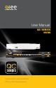
Front Panel
ESCFNRECSHIFT
ENTER
POWERHDD1 2 3 4 5 6 7 8 9 10 11 12 13 14 15 16 NET
QC818 NVR 8 Channels
1 2
7 8 9 10 11 1312 14
3 4 65
Number Item Function
1
Channel
Status Lights
These lights will illuminate to indicate that a particular channel
is recording.
2 Status Lights
Net and HDD will illuminate if there are problems with the
network connection or hard drive, respectively. The power
light will illuminate when the NVR is powered up.
3 IR Sensor Infrared Receiver for Remote Control
4
Directional
Buttons
Navigate through menus.
Change selections in pull down menus (Up/Down buttons)
Toggle settings (Up/Down buttons)
5 Enter Button
Viewing Mode: Go To Menu
In Menu: Acts as mouse click
6 Power Button Puts NVR into Standby mode or wakes it up.
7
Directional
Play Buttons
Play back video forwards or backwards. Pressing the same
button a second time will pause the video.
8
Playback
Speed
Slow or speed up playback - 1/4 speed to 4x speed.
9
Frame
Playback
Move forward or backwards frame-by-frame through video.
Works when video is paused.
10 Shift Button For use in Virtual Keyboard
11 Record Button Begins manual recording on all channels
12
Function
Button
Single Channel Viewing Mode: Opens Color Adjustment
Virtual Keyboard: Backspace function
13 Escape Button Exit any menu or current operation
14 USB Port
For use with flash drive when backing up or updating
firmware. Not for use with mouse.
If the user is logged out, pressing the Enter button will open the Login window. Pressing the
Function button will open the Virtual Keyboard which can be navigated using the directional
buttons. Click Enter to enter a keystroke. Press the Escape button to close the Virtual Key-
board and then press the Enter button to submit your password.
VGA
DC 12V
VIDEO OUT
AUDIO
OUT
IN
RS232
DC 48V
A9
1
10
2
11
3
12
4
13
5
14
6
15
7
16
8
B
NO C
NO C NO C
1 4 85 72 3 6
10
11 12
13
14
9
Rear Panel
Number Item Function
1
POE Power
Input
48V power input for the Power Over Ethernet (POE) block.
2 POE Block
Powers directly-connected cameras and receives video
images.
3 Video Out BNC Connector to television
4 Audio Out BNC Connector for audio output
5 RS232 Reserved for use by manufacturer.
6 Alarm Input
Connect up to 16 external alarm sensors to this block. The
top row of numbers is for the upper block.
7
PTZ and Alarm
Out
Connect up to 3 external alarms using the Normally Open
(NO) or Closed (C) port
Connect the data cables for a PTZ camera into the ports
labeled A and B to control it. “A” is positive (+) and “B” is
negative (-).
8 Power Switch
Turns NVR on or off. Use Shutdown menu function or front
panel power button before switching off.
9 USB Connect the USB mouse to this port
10 Audio In BNC input for audio feed from microphone
11 Network Ethernet cable connection to network
12
HDMI Video
Out
To connect to an HD display
13 VGA Video Out To connect to a VGA monitor (19” or larger)
14
NVR Power
Input
Connect 12V DC power supply here
Your NVR comes with two power supplies. The 48V is exclusively for use in powering the POE
block while the 12V 5A supply is for the NVR itself. The plugs and receptacles are different to
aid in connecting the proper power supply. Do not force or alter these connectors.