
Technical Manual


8
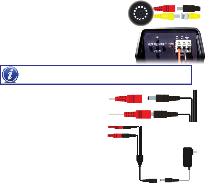
STEP 1.
Connect the BNC and power leads from the camera to
the matching connectors on one end of the power and video
cable.
CONNECTING THE CAMERA TO A SECURITY DVR SYSTEM
CAMERA
STEP 2. For multi-camera packs, connect the power lead on the
other end of the cable to the plug from the power splitter. Or, if
your package includes a power distribution panel, connect the
power lead to one of the power jacks on the panel. Proceed to
Step 4, below.
For single camera packages, connect the power lead to the
power adapter itself. In this case, you may skip to Step 4.
STEP 3. Connect the power lead on the power splitter to the
camera power adapter. DO NOT plug the adapter into an
outlet at this time.
STEP 4.
Connect the BNC connector on the other end of the video/
power cable to a Video In port on the back of the DVR.
Some box cameras require a special adapter with bare wire leads.
The ends of the wires must be inserted into the Positive (+) and
Negative (-) ports on the power input box at the back of the camera.
The power cable plug connects to the attached female power jack on
this adapter.
IMPORTANT! When connecting the power and video cable between the camera and the DVR, the
“male” power end (red plug in the illlustration) connects to the matching power lead on the camera.
Repeat Steps 1 through 4 for all cameras before continuing.
STEP 5. Plug the power adapter into a surge protector* or
turn on the power panel.
*When selecting a surge protector, it is STRONGLY recommended to use one that is UL-1449 rated, for a clamping voltage
of 330 or lower, a Joule rating of at least 400 and a response time of 10 nanoseconds or less.