QD7015P USER MANUAL 1
Thank You for Choosing a Q-See Product! All of our products are backed by a conditional service warranty covering all hardware for 24 months from the date of purchase. Additionally, our products also come with a free exchange policy that covers all manufacturing defects for one month from the date of purchase. Permanent upgrading service is provided for the software and is available at www.Q-See.com. Be certain to make the most of your warranty by completing the registration form online.
Q-SEE PRODUCT WARRANTY 2-year Limited Warranty Thank you for choosing Q-See to provide for your security needs, and welcome to the Q-See community! We stand behind the quality of all of our products, and we want you to know that we’re here to help you should you ever need assistance with your Q-See purchase. To receive full warranty benefits and lightning fast support, register your products at www.Q-See.com.
INTRODUCTION This manual is written for the QD7015P pan-tilt camera and was accurate at the time it was completed. However, because of our ongoing effort to constantly improve our products, additional features and functions may have been added since that time and on-screen displays may change. We encourage you to visit our website at www.Q-See.com to check for the latest product announcements.
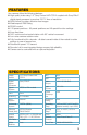
FEATURES Your camera offers the following features: n High quality video using 1/3” Sony Exview HAD CCD-II coupled with Sony Effio-E digital signal processor to produce 700 TV lines of resolution. n 960H format for wider, distortion-free images n Weatherproof IP66 Rating n RS485 control. n 128 preset positions - 80 preset positions and 48 special function settings. n 6mm fixed lens. n 360° continuous horizontal rotation with 90° vertical movement. n Low-noise camera rotation motor.
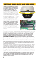
SETTING BAUD RATE AND ADDRESS Unlike conventional security cameras, PTZ cameras require an address and a connection speed to be set in order for them to properly operate. The default settings for this camera are an address of “1” and a baud rate of 2400 and using the Pelco-D protocol. However, if your camera came as part of a bundle, its address may have been set to something other than “1”. Check the Quick Install Poster that came with your bundle for specific details.
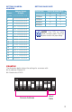
SETTING CAMERA ADDRESS Address SETTING BAUD RATE Address Switch (8 digits) Baud Rate Code 1 2 3 4 5 6 7 8 1 1 0 0 0 0 0 0 0 2 0 1 0 0 0 0 0 0 3 1 1 0 0 0 0 0 0 4 0 0 1 0 0 0 0 0 5 1 0 1 0 0 0 0 0 6 0 1 1 0 0 0 0 0 7 1 1 1 0 0 0 0 0 8 0 0 0 1 0 0 0 0 9 1 0 0 1 0 0 0 0 10 0 1 0 1 0 0 0 0 11 1 1 0 1 0 0 0 0 12 0 0 1 1 0 0 0 0 13 1 0 1 1 0 0 0 0 14 0 1 1 1 0 0 0 0 15 1 1 1 1 0 0 0 0 16 0 0 0 0 1 0 0 0 Switch Number (BIT) 9 10 1200bps 0 0 2400bps 1 0 4800bps 0 1 960
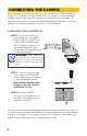
CONNECTING THE CAMERA Before you can operate the camera, you must connect it to a system which can support PTZ operations. There are three sets of connectors - power, video and the bare control wires. This latter connection is covered on the next page. We recommend connecting the camera (at least temporarily) to the DVR to test your settings and connections before mounting it in its final location. POWER AND VIDEO CONNECTION STEP 1.
PTZ CONTROL CONNECTION In addition to connecting the power and video leads to the camera, you must also connect the two control wire leads to the RS485 ports in the alarm block on the back of the DVR. These blocks can vary in layout as shown below, but the ports used by your DVR are generally labelled “RS485”, “RS422”, “PTZ” or “P/Z”. As seen in the picture on the right, the wire leads from the camera are two different colors and are labeled.
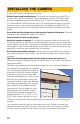
INSTALLING THE CAMERA When installing your camera, it is important to select a proper site not only for field of view, but for other considerations as well: Distance from viewing/recording device. The further the camera is from the DVR or monitor, the higher the chances of signal degradation. Typical 75Ω Video Cable provides acceptable signal at distances up to 200’ (30m). At greater distances, UL-Listed shielded RG59 should be used.
MOUNTING THE CAMERA STEP 1. Run the power/video/data extension cable from the DVR to the camera’s location. STEP 2. Use the mounting bracket to mark the position for the mounting holes. Drill the mounting holes with a 3/16” (5mm) drill bit. If needed, the hole for the cables should also be drilled at this time. It is best to drill a large enough hole to prevent the cable from catching on anything and allowing the cable extending from the camera to be easily pushed through. STEP 3.
WHICH CABLE TO USE? Your cabling needs will depend on the distance between your camera and your DVR. Q-See offers several cables to fit specific needs. These may be purchased from the same location as where you bought your camera, or on our website: www.q-seestore.
OPERATION The your camera can be controlled manually through a PTZ keyboard (if supported by your DVR), or by using the PTZ controls on the DVR to which it is connected. Depending on the software used, it is also possible to control the PTZ camera remotely when you are logged into the DVR via the Internet, a remote monitoring program or a smartphone app.
EXAMPLE 1: SETTING A CRUISE This example is based on using a QT-Series DVR without an attached PTZ keyboard. Your DVR’s specific commands may differ slightly. Please consult your system’s manual. STEP 1. In your DVR’s PTZ settings window, select the Advanced tab and then Preset 1. STEP 2. Rotate the camera to the desired position using the arrow controls. STEP 3. Click Save STEP 4. Select Preset 2. STEP 5. Rotate camera to desired second location. STEP 6.
TROUBLESHOOTING Problem Solution No picture or unstable image Check both the power and video connections to the camera. The on-screen image is blurry. 1. Check for fingerprints or dirt on the lens. 2. Check menu settings. The on-screen image is dim. 1. Check for fingerprints or dirt on the lens. 2. Check monitor settings The on-screen image is dark. 1. Adjust the monitor contrast settings. The screen flickers. Camera may be facing sun, television or computer monitor.