QSTC201/211 IP Camera User’s Manual Q-see Products 8015E.Crystal Dr Anaheim, CA 92807 Website: http://www.q-see.
QSTC201/211 IP-CAMERA USER MANUAL Before using this product Before operating, we strongly advise users to read this manual and keep it handy for later use. This manual provides product instructions but we do not warranty the contents. We reserve the right to amend typographical errors, and the product may change due to software upgrades and product improvements. Any changes will be published in the latest version without special notification.
QSTC201/211 IP-CAMERA USER MANUAL 1 Table of Contents Introduction .................................................................................................................................................... 5 1.1 Product Summary .................................................................................................................. 5 1.2 Check package contents ........................................................................................................ 5 1.
QSTC201/211 IP-CAMERA USER MANUAL 5.5 Network configuration .......................................................................................................... 36 5.5.1 Basic configuration .................................................................................................... 36 5.5.2 IP configuration .......................................................................................................... 38 5.5.3 Wireless configuration ..................................................
QSTC201/211 IP-CAMERA USER MANUAL 1 1.1 Introduction Product Summary This IP-CAMERA is a video surveillance device designed especially for CCTV systems. It uses H.264 compression technology with a high-powered decoding chip, and uses advanced IT technology, such as video encoding and decoding technology, complies with the TCP/IP protocol, SoC, etc… to ensure this system is stable and reliable. This unit consists of two parts: the IP-CAMERA device and central management software.
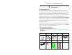
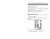
QSTC201/211 IP-CAMERA USER MANUAL Functions of accessories: NO. Accessories 1 2 IP-CAMERA module Power adapter 3 4 5. 6 User manual CD Alarm box Cable 1 Cable 2 Audio line Camera Stand Hex Key 7 8 9 1.3 IP-CAMERA Description The Camera The power adapter output DC 12V, which supplies the power to the IP-CAMERA.
QSTC201/211 IP-CAMERA USER MANUAL 1.3.
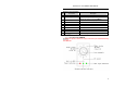
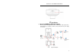
QSTC201/211 IP-CAMERA USER MANUAL 1.3.3 Top View of IPIP-CAMERA CAMERA 2 2.1 Installation Attach IP-CAMERA to Ethernet network The connection of the digital video server is show below. Video input devices, audio input devices and alarms should be connected first, then the power supply is connected.
QSTC201/211 IP-CAMERA USER MANUAL User can connect the PC (Surveillance Center) and IP-CAMERA as shown in the above picture. Before connecting to PC, user needs to connect external devices, and then connect the power. Connecting sensors or alarm boxes is optional and depends on user’s needs. The connection steps are shown below: Step 1: Transfer line 1 connects to alarm box and IP-CAMERA first, and then connect to alarm devices. (For more details please refer to IP-CAMERA hardware installation 2.2).
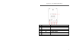
QSTC201/211 IP-CAMERA USER MANUAL Fig 22-3 Connect to alarm box Connection parameter descriptions: Name GND Description Grounding NC Normally Closed Alarm output NO Normally Open Alarm output 5V 5V Power port COM Alarm IN Public port used with NC or NO,connect to alarm output Sensor input 3. Check the Night Vision IR LEDS Power on, the IP-CAMERA starts to work; user can see a circle of lights around the LENS of IP-CAMERA which allow the user to view images clearly in the dark.
QSTC201/211 IP-CAMERA USER MANUAL make sure all anti-virus software in the computer is disabled so that CMS can install correctly. • System requirements Supported Operating Systems: Operating Comments system Windows XP Windows XP SP2 or most recent patch, DirectX 9.0c or above Windows Vista Windows Vista DirectX 10.
QSTC201/211 IP-CAMERA USER MANUAL HDD 250GB Notice: The above recommended specifications are for CIF resolution. The AMD hyper-3800+ and X64 series chips have not been tested; If user wants to have real-time live view with CIF resolution (352x240), the max connection number is 16 on one computer; If user wants to have real-time live view with D1 resolution (704x480), the max connection number is 4 on one computer. 2.3.1 Install process 1.
QSTC201/211 IP-CAMERA USER MANUAL Figure2-5 Choose the installation destination 3. The default installation destination folder is “C:\Program Files”, user can click “Browse” button to change it. After selecting the destination, click “Next” to enter the next step shown as Fig 2-6: Figure2-6 selects a folder to install in 4. Click “Next” to start installing and display Fig 2-7: Figure2-7 the rate of installation progress 5.
QSTC201/211 IP-CAMERA USER MANUAL Figure2-8 Setup Complete 6. Click “Finish” to complete setup, and see the “Control Center” icon on the desktop. 7. Double click CMS icon to start the software, the default user name is “system”, and password is “123456”, user can change it as shown in the corresponding chapter, for detailed introductions refer to “user manager” in user manual.
QSTC201/211 IP-CAMERA USER MANUAL Figure2-9 Preview interface 8. Add device: User can add video monitor device or sub region under the heading of add region. Step 1: Enter into the System Configuration menu, click 'Device Manager , input the region name in 'Region' textbox.
QSTC201/211 IP-CAMERA USER MANUAL Step 2: Click Fig 2-11: button; 'Add Device' dialog box will pop up refer to Fig 2-11 Add device Step 3: If the monitor device exists with the PC at the same LAN, click the “Search device” button, CMS will search for the compatible device in LAN and list the details in the “Device search” dialog box.
QSTC201/211 IP-CAMERA USER MANUAL Step 2: Clicking ‘Device Manager click enters into “Device manager”, icon, add group name. Refer to Fig 2-13 Fig 2-13 Add group Step 3: Select the channel in the “Device list” edit box, click and add the channel into “Channel group” edit box.
QSTC201/211 IP-CAMERA USER MANUAL 3 Internet Explorer Remote Access The network service default settings are shown below: IP address: 192.168.0.201 Subnet Mask: 255.255.255.0 Gateway: 192.168.0.1 HTTP: 80 Data port: 9008 When using the IP-CAMERA for the first time, please connect the device using the above default settings, and reconfigure the setting according to your network. Here we are using IE browser (above 6.0 versions) as an example; for operation using CMS please refer to CMS user’s manual. 3.
QSTC201/211 IP-CAMERA USER MANUAL Step 2: Open the IE Browser, input the default address of IP-CAMERA and confirm, the IE browser will download an Active X control automatically.
QSTC201/211 IP-CAMERA USER MANUAL 3.2 WAN Setting up the router: Step1: Connect according to above steps in LAN, enter into System Configuration—Network configuration—Basic configuration, setup the port numbers refer to Fig 3-4: Fig 3-4 Port setup Step 2: Enter into System Configuration—Network configuration—IP configuration, change IP address refer to Fig 3-5: Fig 3-5 IP setup Note: The steps above should be saved after changing the port and IP address. Log back into the device with the saved setting.
QSTC201/211 IP-CAMERA USER MANUAL Step3: Enter into the router’s management interface through IE browser; forward the port of IP-CAMERA to the IP address of the camera in the “virtual server”. Or whatever the category is called on the router you are using.
QSTC201/211 IP-CAMERA USER MANUAL 4 Remote Preview 4.1 The remote viewing interface is shown below: Fig 4-1 remote preview interface Symbol and function Definitions: ① Motion Indicator ② Picture snapshot ③ Click this button to enable two-way ④ Zoom in and out ⑤ Return to normal view ⑥ System Setup ⑦ Search for video files talk. Note: Before doing audio talk; users should make sure microphone and earphone connected with IP-CAMERA and PC work normally.
QSTC201/211 IP-CAMERA USER MANUAL 4.2 Configuration: Video Stream, Enable Audio Click right mouse, a pull-down list will appear as shown below: Fig 4-2 Right key sub-menu Master Stream/Second Stream: select the video stream. This IP-CAMERA supports master stream and sub stream. Master stream has higher frame rate, max 30fps for every channel, but it needs higher network bandwidth to run effectively; Second stream has low frame rate, max 3fps for every channel, it requires lower network bandwidth.
QSTC201/211 IP-CAMERA USER MANUAL Snap pictures: 1. Select a channel, click “Snap” icon, this will display Fig 4-3: Fig 4-3 Single snap 2. User can take multiple pictures, select “frames”, such as 3, tick off “Title” and “Time”, capture title and time will display simultaneously. Refer to Fig 4-4: Fig 4-4 Multiple snap 3. Click “Browse” to set location to save file. Click “Save” to save pictures to HDD on the computer and the save folder windows will open. 4.
QSTC201/211 IP-CAMERA USER MANUAL 4.
QSTC201/211 IP-CAMERA USER MANUAL 5 Remote Live Surveillance 5.1 Main Menu Setup User can remotely setup the parameters of the device. Functions of remote configurations include: system configuration, channel configuration, alarm configuration, network configuration, notification configuration and advance configuration. User should first select the server on the menu list on the left, and then setup the relative parameters.
QSTC201/211 IP-CAMERA USER MANUAL Parameter Date format Meaning Display time in live view. Three formats: YY-MM-DD, DD-MM-YY, MM-DD-YY Fig 5-1 system configuration—server basic configuration interface 5.2.2 Date & Time configuration Setting steps: 1. Enter into "system configuration" –“Date & Time” refer to Figure 5-2: 2. Choose the right "Time Zone" according to user’s location. 3. Select “Modify Time ", user can setup time by select the “Synchronize with NTP Server” or “Set manually”.
QSTC201/211 IP-CAMERA USER MANUAL 5.2.3 SD Card Setup steps: 1. Enter into "system configuration" –“Date & Time” refer to Figure 5-3: 2. Usage status: Blue pane means used; red pane means unused. 3. Pressing "Eject card" terminates writing data to SD card, then it can be ejected safely. Note: Use of the SD card function should be coordinated with Motion alarm and Sensor alarm, when alarm is triggered (refer to 5.3 Alarm configuration for details), pictures can be stored on the SD card.
QSTC201/211 IP-CAMERA USER MANUAL 5. Press the "Save" button to save the settings. Fig 5-4 channel configuration—basic configuration interface 5.3.2 Image configuration 1. Enter into "Channel configuration"—“Image configuration” refer to Figure 5-5: 2. Select the channel to be setup using the "Channel Number" list box. 3. Press "Load Default" button to reset the default value of brightness, contrast, hue, saturation. 4. Move the scroll bar to set the value of the brightness, contrast, hue, saturation. 5.
QSTC201/211 IP-CAMERA USER MANUAL 5.3.3 Network image configuration 1. Enter into "Channel configuration"-- "Network image configuration" refer to Figure 5-6: Fig 5-6 channel configuration—network image configuration interface 2. Select the channel which needs to be setup on the "Channel” pull down list. 3. Select the resolution of the single frame image on the "Resolution" pull down list. 4. Select the data stream type on the "Bit rate type" pull down list. 5.
QSTC201/211 IP-CAMERA USER MANUAL Parameter Meaning Frame rate Max 30 fps Video quality The quality of video image Max 15 fps 5.4 Alarm configuration Alarm configuration includes seven submenus: motion detection, motion alarm, motion schedule, sensor alarm, sensor schedule, other alarm and alarm out. 5.4.1 Motion detection 1. Enter into “Alarm configuration"--"Motion detection" refer to Figure 5-7: 2. Select the channel to set motion detection parameters at the "Channel Number" pull down list. 3.
QSTC201/211 IP-CAMERA USER MANUAL will be triggered when there was an alarm. 5. Select the matched channel in “Trigger PTZ” text box, select “To preset” or “Start cruise”, when motion detection triggers alarm, the PTZ install stand of the device will move to corresponding preset point or cruise line. 6. Press the "Save" button to save the settings. Fig 5-8 alarm configuration—motion alarm interface 5.4.
QSTC201/211 IP-CAMERA USER MANUAL Press the "Save" button to save the settings. Note: Day schedule is better than Week schedule. Fig 5-9 alarm configuration—motion schedule interface 5.4.4 Sensor alarm 1. Enter into “Alarm configuration"--"Sensor alarm", refer to Figure 5-10: 2. Select the sensor which needs to be setup on the "Sensor" pull down list, and set the sensor type: NO or NC. 3. Select the "Enable alarm" check box, all functions under this interface will be activated. 4.
QSTC201/211 IP-CAMERA USER MANUAL Fig 5-10 alarm configuration—sensor alarm interface 5.4.5 Sensor schedule Enter into “Alarm configuration"—“Sensor schedule” refer to Figure 5-11: Week schedule User can set the recording time from Monday to Sunday for recording everyday of a week. 1. Select the sensor which needs to be setup on the "Sensor" pull down list. Note: The length bar is for each day of the week divided into the 24 hours of a day.
QSTC201/211 IP-CAMERA USER MANUAL Fig 5-11 alarm configuration—sensor schedule interface 5.4.6 Other alarm 1. Enter into “Alarm configuration"— "Other alarm" refer to Figure 5-12: 2."Alarm type" default is video loss. 3. Select the channel which needs to be setup on the "Channel Number" pull down list. 4. Select "Alarm out" in the "Trigger alarm out" textbox, which is optional. 5. Press the "Save" button to save the settings.
QSTC201/211 IP-CAMERA USER MANUAL 5.4.7 Alarm out 1. Enter into “Alarm configuration"— "Alarm output" refer to Figure 5-13: 2. Select the alarm out number, alarm holding time and alarm name on the "Alarm out”, “Alarm holding time” and “Name” pull down list respectively. 3. Press the "Save" button to save the settings. Fig 5-13 alarm configuration—alarm out Please refer to the following table for parameters and instructions of alarm out.
QSTC201/211 IP-CAMERA USER MANUAL 4. Enable UPNP Double-click the “My Network Places” icon on the desktop in PC, select “Show icons for networked UPnP devices” in the “Network Tasks” list box, an information window will pop up, click “YES” button, “Windows Components Wizard” dialog box will pop up as shown in picture below, press “Next” to continue. After finishing the installation of configured components, the UPnP icons will display.
QSTC201/211 IP-CAMERA USER MANUAL 5.5.2 IP configuration 1. Enter into "Network configuration"--"IP configuration", refer to Figure 5-15: There are three Options for setup IP: Static IP, dynamic IP and PPPOE. 2. Static IP: users manually input the IP address, subnet mask, gateway and DNS. 3. Dynamic IP: router will distribute IP address to device automatically. 4. PPPOE: users manually input the user name and password for the network connection that they get from their internet service provider. 5.
QSTC201/211 IP-CAMERA USER MANUAL Please refer to the following table for parameters and instructions of IP configuration.
QSTC201/211 IP-CAMERA USER MANUAL 5-17: 2. Select “wireless switch”, click “refresh” button, available wireless networks found by device will display in the “Available network” list box on the right. User can setup relative parameters according to available wireless networks. 3. SSID, channel, authentication mode and encrypt type, password are the same as the user’s wireless router settings. 4.
QSTC201/211 IP-CAMERA USER MANUAL Fig 5-18 network configuration-- DDNS configuration interface 2. Press the "Save" button to save the settings. Please refer to the following table for parameters and instructions of DDNS configuration. Parameter DDNS server Meaning Address of the website provided by domain name supplier. The options: www.dyndns.com and myq-see.
QSTC201/211 IP-CAMERA USER MANUAL 5.6 User configuration Enter into "User configuration" refer to Figure 5-19: Fig 5-19 User configuration interface Add user: 1. Click "Add" button, "Add user" dialog box opens, refer to Figure 5-20: Fig 5-20 Add user dialog box 2. Input user name in "User Name" textbox (only letters).
QSTC201/211 IP-CAMERA USER MANUAL device on this PC in network only. If the MAC address was ““00:00:00:00:00:00” it can be connected to any computers. 5. Click “OK” button, new added user will be displayed in the user list. Modify user: 1. Select the user who needs to modify password and physical address in the user configuration list box. 2. Click “Modify” button, “Modify user” dialog box pops up, refer to Figure 5-21: Fig 5-21 Modify user dialog box 3.
QSTC201/211 IP-CAMERA USER MANUAL Please refer to the following table for parameters and instructions of user configuration. Parameter User Name User Type Binding MAC address Password Confirm Password Meaning User name to operate the logon client end Type of user: normal user, advanced user and super administrator The MAC addresses of users accessing the server which should setup according to actual MAC address of the server.
QSTC201/211 IP-CAMERA USER MANUAL Fig 5-22 Notification configuration—mail configuration interface 5.8 Advanced configuration Advanced configuration includes three submenus: upgrade, security configuration and default configuration 5.8.1 Upgrade Enter into advanced configuration—upgrade, refer to Figure 5-23: 1. Click “Browse” button to select the save path of the upgrade file 2. Click “upgrade server firmware” button, start upgrading the application program 3.
QSTC201/211 IP-CAMERA USER MANUAL address” can’t operate at the same time. Fig 5-24 advanced configuration—security configuration interface 5.8.3 Default configuration Enter into advanced configuration—default configuration refer to Figure 5-25: Fig 5-25 advanced configuration—default configuration interface Click “Load default” button to restore all system settings to original value, except for IP address. 5.8.
QSTC201/211 IP-CAMERA USER MANUAL 6 Video Search Click “video search” icon, to search the images which are saved on the SD card refer to Figure 6-1: 1. Select date in the “calendar”, check “motion detection” and/or “sensor”, click “search” button, the snapped pictures that triggered the alarm will display in the list box. 2. Double click a file name in the list box and you can check the snapped pictures. 3. Click “save” icon select the save path for the file on PC.
QSTC201/211 IP-CAMERA USER MANUAL 7 Mobile Surveillance This IP-CAMERA supports mobile surveillance by cell phones with Windows mobile pro and Symbian operating systems. Below are the details of the supported versions. Please check the operation system version of mobile phone before using. Operation system Compatibility Windows Mobile 2003 for Smartphone not supported Windows Mobile 2003 for Pocket PC supported Windows Mobile 5.0 for Smartphone Windows Mobile 5.
QSTC201/211 IP-CAMERA USER MANUAL OS v9.3 Symbian S60 5th Edition-Symbian OS v9.4 supported Symbian S60 5.1 Edition-Symbian OS v9.5 supported 7.1 Accessing by Phones with Windows Mobile Pro Please use cell phones or PDAs with WinCE versions supported by this unit. First activate the network access on the mobile phone, and then run “Internet Explorer”. STEP 1: Input the public IP address you need to use to connect as shown below: STEP 2: Click on the software name. A dialog box will pop up.
QSTC201/211 IP-CAMERA USER MANUAL STEP 4: PCam will be opened after installed. STEP 5: Input the server’s address, ID, and password respectively in the columns of “Server”, “User”, and “Password”. Then click “Go” to login to the DVR. It will show the picture if accessed successfully. STEP 6: Camera 1 is the default display after login. Change the camera in the drop down menu of “Channel”.
QSTC201/211 IP-CAMERA USER MANUAL Note: User name and password here are the same as that used on the DVR. The defaults are user name “admin” and password “123456”. 7.2 Accessing by Phones with Symbian Please use smart phones or PDAs with Symbian version supported by this unit. STEP 1: First enable the network access on mobile phone, and then run Web browser. STEP 2: Input the DVR server’s IP address in a new-built bookmark. Click this bookmark to connect with the DVR.
QSTC201/211 IP-CAMERA USER MANUAL STEP 5: A Scam shortcut icon appears on the system menu after finished. STEP 6: Run Scam program. STEP 7: Click Options--->Settings to enter login interface.
QSTC201/211 IP-CAMERA USER MANUAL STEP 8: Input the server’s address, ID and password respectively. Then click OK to login to the DVR. STEP 9: It will show the camera after accessing successfully.
QSTC201/211 IP-CAMERA USER MANUAL DVR. The defaults are user name “admin” and password “123456”. 7.3 Accessing from iPhones At present, the software only supports iPhone os2.2 and above, if phone firmware is lower than this version please upgrade it.
QSTC201/211 IP-CAMERA USER MANUAL Step 3: Click SuperCam, to enter into “introduce” interface and click FREE”, it will change into “INSTALL” Step 4: Enter into iTunes Store password, click “OK” the below interface will 55
QSTC201/211 IP-CAMERA USER MANUAL display: Note: if this is the first time you are operating please enter your user ID; if you do not have a Store account, you will need to create one. Step 5: Download the program and install it. After installing, the SuperCam icon will display. Click this icon, the program interface will appear Step 6: Click “System setting”, to enter into login interface. Enter server’s IP address (or domain name), user’s ID and password. Click Back to save.
QSTC201/211 IP-CAMERA USER MANUAL Step 7: Click Live View, the default Cam1 picture will be displayed. Click capture picture. Click to to enter PTZ mode.
QSTC201/211 IP-CAMERA USER MANUAL Step 8: Click Image View on program interface to view the captured picture. Click or to switch to next or previous picture. Click picture. to delete the current Method two: Download SuperCam from iTunes, and synchronize it to iPhone Step 1: Install iTunes on PC, and open it.
QSTC201/211 IP-CAMERA USER MANUAL the data cable. When prompt message appears click “Continue”, refer to below interface. Input user’s ID and password. Step 2: Click “iTunes Store” on the left column, search for “SuperCam”.
QSTC201/211 IP-CAMERA USER MANUAL Step3: Click searched “SuperCam”, refer to below picture. Step 4: Click“GET APP”, an input box will pop up. Enter user’s ID and password, then press “Get”. It will download applicaton to the computer.
QSTC201/211 IP-CAMERA USER MANUAL “Applications”. Check ”Sync applications” and “SuperCam”. Then click “Apply” in the lower-right corner, and wait for installation to finish. Step 6: After installation finishes, return to main interface of iPhone, where the camera icon will be displayed. Step 7: Click camera icon; the program interface will appear. The following setting steps are the same as method one “Step 5, 6, 7, 8”.
QSTC201/211 IP-CAMERA USER MANUAL 8 Questions & Answers 1. Q: I forgot the password, how can I reset it? A:Press “RESET” button for 4 seconds to restore to default status. Note: Default IP: 192.168.0.201 User name: admin Password: 123456 2. Q:I can not connect to devices through IE browser, what can I do to solve the problem? A: Please check the network cable connections and make sure they are connected well. B: IP is not available. Reset the IP and make sure it is correct.
QSTC201/211 IP-CAMERA USER MANUAL select Security------Custom Level….refer to Fig 4-1 Fig 4-1 Fig 4-2 Enable all the sub options under “ActiveX controls and plug-ins”, refer to Fig 4-2 then click ok to finish setup. b. Other plug-ins or anti-virus could block ActiveX. Please turn off anti-virus programs and disable other plug-ins using the Tools – Manage add-ons option. After you install the ActiveX control you can turn the other plug-ins back on until you find the one that was causing the problem. 5.
QSTC201/211 IP-CAMERA USER MANUAL 6. Q:How can I set this IP Camera up on a wireless router? A: 1. Connect camera to the Router using the network cable provided 2. Make sure the PC is connected to the same Router 3. Check the IP address of the Router by running IPCONFIG from the PC ( go to command prompt and type in ipconfig). Note the ip address. As an example here the IP is 192.168.1.100 4. Install the CMS program. 5. Run IP TOOL. Default login is system and password is 123456 6.
QSTC201/211 IP-CAMERA USER MANUAL 15. If you want to remotely view this camera from outside the network, you need to forward port 80 and 9008 to the IP address of the camera in the Router. (There are complete instructions on how to do this in the manual). 7. Q:I can not connect to a wireless router, what can I try? A: Check the status of the wireless router. Please make sure the router is open or enabled. B: Check the router and the device port.
QSTC201/211 IP-CAMERA USER MANUAL 9 Specifications 66
QSTC201/211 IP-CAMERA USER MANUAL 67
QSTC201/211 IP-CAMERA USER MANUAL 10 Q-See Product Warranty Thank you for choosing our products. All of our products users have a conditional free warranty repair service for hardware within 12 months starting from purchase date, and a free exchange service within one month (valid for manufacturing defects). Permanent upgrading service is provided for the software.
QSTC201/211 IP-CAMERA USER MANUAL Customer Information Card User’s Name Mr./Mrs.
QSTC201/211 IP-CAMERA USER MANUAL The material in this document is the intellectual property of our company. No part of this manual may be reproduced, copied, translated, transmitted, or published in any form or by any means without our company’s prior written permission. 1. Our products are under continual improvement and we reserve the right to make changes without notice. But no guarantee is given as to the correctness of its contents. 2.