QSTD2400 Series DVR User’s Manual QSTD2404/QSTD2408/QSTD2416 Digital Video Recorders User’s Manual For H.
QSTD2400 Series DVR User’s Manual CAUTION z Please read this user’s manual carefully to ensure that you use the device correctly and safely. z This manual is for the 4-channel, 8-channel and 16-channel QSTD2400 Series DVRs. In this manual, we use the QSTD2408 200FPS 8-channel DVR as an example. All examples and pictures used are of this model. z As products update the contents of this manual are subject to change without notice.
QSTD2400 Series DVR User’s Manual Table of Contents Table of Contents ................................................................................................. iii CHAPTER 1 Introduction ................................................................................. 1 1.1 DVR Introduction........................................................................................ 1 1.2 Main Features ............................................................................................
QSTD2400 Series DVR User’s Manual CHAPTER 5 Managing the DVR .................................................................... 38 5.1 Formatting Hard Drives ............................................................................ 38 5.2 Updating Firmware ................................................................................... 38 5.3 Loading Default Setup.............................................................................. 39 5.4 Checking System Information .......................
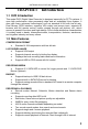
QSTD2400 Series DVR User’s Manual CHAPTER 1 Introduction 1.1 DVR Introduction This model DVR (Digital Video Recorder) is designed especially for CCTV systems. It uses high performance video processing chips and an embedded Linux system. It also uses many advanced technologies, such as standard H.264 with low bit rate, Dual Stream, SATA interface, supports VGA output and mouse input, supports IE browser with full remote control, mobile viewing through cell phones, etc.
Digital Video Recorder User Manual ALARM • 4/8/16 channel alarm input and 4 channel alarm output available depending on model. • Supports schedule for motion detection and sensor alarm • Supports pre-recording and post recording • Supports linked channels recording once motion or sensor alarm triggered on one channel. • Supports linked PTZ presets and auto cruise of the corresponding channel. PTZ CONTROL • Supports various PTZ protocols. • Supports various PTZ presets and 32 auto cruise tracks.
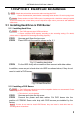
QSTD2400 Series DVR User’s Manual CHAPTER 2 Hardware Installation Notice: Check the unit and the accessories after receiving the DVR. Please disconnect the power before connecting other devices. Do not hot plug in/out Notice: Some vendors sell this DVR as part of a package with a hard drive already installed. If your unit already has a hard drive you can skip these steps unless you want to add additional hard drives. 2.1 Installing Hard Drive & DVD Burner 2.1.1 Installing Hard Drive Notice: 1.
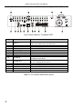
Digital Video Recorder User Manual 2.2 Front Panel The Front Panel Layout is shown as Fig 2.3 Front Panel. Fig 2.3 Front Panel 1 2 3 4 5 6 7 8 9 10 11 Heat release window HDD lock Number buttons Multi-screen button Direction Enter button Indicator lights Shuttle Power HDD Status lights INFO 12 13 14 15 16 17 18 19 20 21 22 AUTO/- P.T.Z.
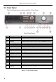
QSTD2400 Series DVR User’s Manual 2.3 Rear Panel 2.3.1 Rear Panel Layout The Rear Panel Layout for 8 Channel DVR is shown as Fig 2.4 Rear 8Ch. Fig 2.
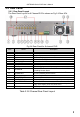
Digital Video Recorder User Manual The Rear Panel Layout for 16 Channel DVR is shown as Fig 2.4 Rear 16Ch. Fig 2.5 Rear Panel for 16-channel DVR Item Name 1 Spot out 2 3 4 5 6 8 9 Audio out S-video PS/2 port USB MOUSE RJ45 PORT VGA port COM port 10 ALARM IN 11 ALARM OUT 12 13 14 15 16 Power LOOP OUT e-SATA Video in Video out Description Connect to monitor as an AUX output channel by channel.
QSTD2400 Series DVR User’s Manual The Rear Panel Layout for 4 Channel DVR is shown as Fig 2.4 Rear 4Ch. Fig 2.
Digital Video Recorder User Manual 2.3.2 Installing Sensor Alarm The DVR has 4,8, or 16 channel alarm input (depending on model) and four-channel alarm output. Alarm Input: The alarm input is triggered by electric level (High: 5V, Low: 0V). Users can connect external sensors, like gas detector, smoke detector and infrared detector. Once the DVR detects that the electric level meets the setting user’s make, it will trigger DVR recording or alarm out. For example, a sensor is connected to alarm input1.
QSTD2400 Series DVR User’s Manual 2.4 Remote Control The remote control uses two AAA size batteries and works after loading batteries as follows: STEP1 Open the battery cover of the Remote Control STEP2 Insert batteries. Please make sure the poles (+ and -) are correct STEP3 Replace the battery cover Notice: If the remote control does not work, check the following: 1. Check the poles of the batteries. 2. Check the remaining charge in the batteries. 3.
Digital Video Recorder User Manual 2.5 Controlling with Mouse 2.5.1 Connect Mouse DVR supports PS/2 or USB mouse through the ports on the rear panel, please refer to Fig 2.10 Remote Control. Notice: If mouse is not detected or doesn't work, try the following: 1. Unplug/re-plug several times 2. Power off/on several times 3. Try another mouse 2.5.2 Using a Mouse The structure of the main menu is shown in Fig 2.10 Remote Control In live Mode: Click left button on one camera to display full screen.
QSTD2400 Series DVR User’s Manual CHAPTER 3 Basic Operating Instructions 3.1 Power On/Off Notice: Before you power on the unit, please make sure all the connections are good. 3.1.1 Starting There are two ways to start the DVR. One way is to connect the power source, switch on the power button near the power port on the rear panel, and the system will start up.
Digital Video Recorder User Manual Symbol Meaning Symbol (green) (yellow) HDD Free Manual recording Motion detection recording Current working Hard Drive Free space on current HDD Meaning Audio disabled in live mode Audio enabled in live mode (blue) (red) Space Scheduled recording Alarm recording Size of current HDD USB devices connected HDD full 3.1.2 Close When you shut down the system, please strictly follow shut down procedures.
QSTD2400 Series DVR User’s Manual 3.2 Login & User Management Users can logout and login to the DVR system. Users cannot do any other operations except changing the multi-screen display when logged out. They are logged out when the system starts or restarts. Login: To log in, please press right mouse to show the control bar. Press Login, Search, or System etc. A login window will appear, asking for ID and password as in Fig 3.4 Login. Fig 3.4 Login Notice: The default login is admin and 123456.
Digital Video Recorder User Manual Add & Delete users: This unit has a default administrator and two user groups, advanced and normal user. It supports 1 administrator and 15 users total. Administrator can add or delete other users, and change their group level. Administrator cannot be added or deleted. Press right mouse to show the control bar. Enter Menu---->System. STEP1 Enter USER configuration. Click Add button, please see Fig 3.6 Add User. Fig 3.6 Add User STEP2 Input user name and password.
QSTD2400 Series DVR User’s Manual 3.3 Recording 3.3.1 Record Setup Users need to install and format a HDD, unless the unit came with a hard drive already installed, and set all the recording parameters before recording. There are four recording modes. Users can enable them simultaneously. They have different priorities as below. Motion detection recording > Sensor recording > Manual recording > Scheduled recording Press right mouse to show the control bar, refer to Fig 4.1 Control Bar.
Digital Video Recorder User Manual 3.3.2 Manual Recording Just press the REC button on the front panel after exiting system setup. Press the Stop button to stop recording. You can also press the REC button on remote controller, click again to stop, or click the REC button on the control bar with mouse, click again to stop. 3.3.3 Scheduled Recording Users can set different schedule times for every day in the week. If you want a special schedule for one day, you can use Holiday function.
QSTD2400 Series DVR User’s Manual 3.3.4 Motion Detection Recording This unit supports recording channels and PTZ linking. This means it will record on any cameras, or trigger any speed dome to go to presets or do auto cruise once motion is detected. STEP1 Enter MOTION configuration and select camera or channel Fig 3.10 Motion Detection Setup STEP2 Put check mark in Enable Detection box first, and then enter Area to set Sensitivity and detection Area.
Digital Video Recorder User Manual STEP4 Select alarm out and recording channels. It can trigger any alarm out and cameras to record once motion is detected. STEP5 Enable or disable Buzzer on board. Select speed dome and enable preset or auto cruise (if you are using a PTZ camera). Press OK to save STEP6 Set Hold time This is the length of time between two consecutive motion alarms. If a second motion is detected during Hold time, it is recognized as a continuous part of the first motion event.
QSTD2400 Series DVR User’s Manual 3.4 Playback This unit supports time search and event search. It displays full screen or 4 screens in playback. Click right mouse to show the control bar, refer to Fig 4.1 Control Bar. Click Search, the window below will appear on screen. Fig 3.13 Search Menu Time Search: STEP1 Enter Search configuration, select Time Search. A window will appear as in Fig 3.14 Calendar Search. If there are recordings in a day, the date will be highlighted. Fig 3.
Digital Video Recorder User Manual STEP3 This unit has full screen and 4 screen playback. Select the screen display mode and the channels. STEP4 If want to change the date, press Date button. Set hour and minutes of start time. If it recorded at that time, the boxes will show green. STEP5 Click Play button. It will play from the time point you set. STEP6 Click the relative buttons on the screen to do fast forward/backward, pause, stop, and change the screen mode and re-search, See Fig 3.16 Playback.
QSTD2400 Series DVR User’s Manual 3.5 Backup & Viewing This unit supports backup to built-in SATA DVD Writer (optional equipment), or to USB Flash drive, through the USB port on the front panel. Users can also make backup by IE browser via internet, refer to 6.3.2 Remote Backup. Taking USB flash backup as an example, Press right mouse button to show the control bar, refer to Fig 4.1 Control Bar. At DVR location: STEP1 Enter Backup mode, see Fig 3.18 Backup Setup Fig 3.
Digital Video Recorder User Manual STEP6 It will show “Backup complete” after finished, as shown below. Check & View: Users can view the backup with the third party software like realplayer, and Windows Media Player directly in addition to the special software attached with backup. Below are the steps of viewing the backup with the special software. STEP1 Move the backup device or disc to a computer. Enter the backup folder and open the viewer. Fig 3.
QSTD2400 Series DVR User’s Manual backup, as in Fig 3.21 Choose Backup Folder. Fig 3.21 Choose Backup Folder STEP3 Set the date and channels. It will show the recorded video in area ③ with green light at the bottom as shown in Fig 3.22 Backup Data Search. Fig 3.22 Backup Data Search If using event search, it will list event files at the bottom of area① STEP4 Drag the slide bar to the start time point, click play button to view. It supports multi screen display.
Digital Video Recorder User Manual Tab 3.1 Backup View Control STEP5 DVR supports AVI conversion. Click “Change File to AVI”. The converter will appear. STEP6 Click Browse to choose the folder that contains the video backup first. Set the start/end time, select the channels, and then Click search button. It will show backup files in the file display area as in Fig 3.24 AVI Converter: Fig 3.24 AVI Converter STEP7 Select the files.
QSTD2400 Series DVR User’s Manual Fig 3.25 PTZ Setup STEP2 Set protocol, baud rate, address according to the parameters of the speed dome. STEP3 Click Set button at right of Preset. Here users can setup presets (see Fig 3.26 Set Presets), and adjust the speed dome. Select a preset and click Save to a preset. Users can set up to128 presets. Fig 3.26 Set Presets STEP4 Click Set button at right of Cruise. Here users can set cruise track, as Fig 3.27 Set Cruise.
Digital Video Recorder User Manual Click ↑,↓,↑,↓ to adjust the sequence of the presets in the auto cruise. Click Save to save and return to the previous interface. button to save and exit. Press right mouse button to STEP6 Click show the control bar. Click PTZ to enter PTZ control, shown as Fig 3.28 PTZ Control. Fig 3.28 PTZ Control STEP7 Select the speed dome. Click the direction buttons to move the camera. Click the relative + and – buttons to adjust zoom, focus, IRIS and speed.
QSTD2400 Series DVR User’s Manual CHAPTER 4 Menu Setup Guide 4.
Digital Video Recorder User Manual 4.2 Main Menu Setup Click right mouse, or press ENTER button on the front panel, the control bar will show on the bottom of the screen as Fig 4.1 Control Bar. Fig 4.1 Control Bar Move the cursor to Menu and click, the option menu will show as Fig 4.2 Pop up Menu Fig 4.2 Pop up Menu Select System. A graphic user interface will show as Fig 4.3 System Setup. Fig 4.
QSTD2400 Series DVR User’s Manual 4.2.1 Basic Configuration Click BASIC to enter Basic Configuration shown as Fig. 4.4. Basic Configuration Fig 4.4 Basic Configuration Here users can set video system, menu language, audio, time and authorization check. The following are explanations of each option. Device name: The name of the unit. It may display on the client end or CMS, which helps users to recognize the unit remotely. Device ID: It is used to identify multiple devices at the same place.
Digital Video Recorder User Manual Camera name: Set camera name. It can be a combination of numbers, letters and symbols. Show name: Display camera name in live view. Show time: Display the time in live view. Dwell time: It is available for both Sequence and SPOT simultaneously. This unit has 2-channel video output, refer to 2.3.1 Rear Panel . One is main output, and the other is spot output. Users can set the display time of cameras in auto dwell and spot out. SPOT enable: Enable spot output.
QSTD2400 Series DVR User’s Manual Video quality: There are five options from lowest to highest. The higher the value is, the clearer the recorded picture is, but the more hard drive is taken up. Frame rate: Set recording frame rate. Audio: Enable audio to record. Time stamp: Record the current time on the video file if checked. Record: Switch on/off recording function for every camera.
Digital Video Recorder User Manual 4.2.5 Alarm Configuration Click ALARM to enter Alarm Configuration shown as Fig 4.9 Alarm Configuration. Fig 4.9 Alarm Configuration Here users can set sensor type, alarm trigger and alarm hold time. The following are the explanations of each option. Device type: NC and NO (Normal Close and Normal Open). Set the value according to the alarm signal type of the sensors. Enable: Enable sensor alarm.
QSTD2400 Series DVR User’s Manual 4.2.6 Motion Configuration Click MOTION to enter Motion Configuration as Fig 4.11 Motion Configuration. Fig 4.11 Motion Configuration Here users can set motion sensitivity, detection area, and alarm out. The following are the Explanations of each option. Enable: Enable motion detection. Trigger: Setup similar to that of sensor alarm.
Digital Video Recorder User Manual 4.2.7 Network Configuration Click NETWORK to enter Network Configuration shown as Fig 4.13 Network Configuration. Fig 4.13 Network Configuration This unit supports DHCP, PPPoE, and DDNS. Users enable network function, and configure IP address, DDNS, and transmission video parameters here. The following are the explanation of each option. HTTP port: The default is 80. If users change the value, they need to add the port number when typing IP address in IE address blank.
QSTD2400 Series DVR User’s Manual Fig 4.14 DDNS Configuration Server: Select DDNS server. User name and Password: Input account information. This unit supports dual stream. Users can set picture quality, frame rate, and resolution separately for network, according to the network bandwidth. Click Video to enter the configuration interface shown as Fig 4.15 Network Video Configuration. Fig 4.15 Network Video Configuration Video quality: Network picture quality.
Digital Video Recorder User Manual 4.2.8 P.T.Z Configuration Click P.T.Z to enter PTZ Configuration as Fig 4.16 PTZ Configuration. Fig 4.16 PTZ Configuration Here users can set protocol, baud rate, address, presets, and auto cruise tracks. The following are the explanations of each option. Protocol, Baud rate, Address: Please set the values according to the settings of the speed dome. Speed: Set the speed of speed domes. Preset, Name: Select a preset and rename it.
QSTD2400 Series DVR User’s Manual 4.2.9 User Configuration Click USER to enter User Management interface shown as Fig 4.18 User Configuration. Fig 4.18 User Configuration Administrator can add, delete users, and change their authorizations. Please refer to 3.2 Login & User Management. Notice: System supports one administrator and a maximum of 15 users. 4.2.10 Tools Configuration Click TOOLS to enter Tools Configuration shown as Fig 4.19 Tools Manager. Fig 4.
Digital Video Recorder User Manual CHAPTER 5 Managing the DVR 5.1 Formatting Hard Drives If you want to record, it is necessary to format the hard disk first. If not formatted, it will show the position of the disk, free space, and total space showing as 0M at the bottom of the main viewing screen. STEP1 Enter TOOLS Configuration, refer to 4.2.10 Tools Configuration. Press Disk Manager, a window will pop up shown as Fig 5.1 Disk Manager. Fig 5.
QSTD2400 Series DVR User’s Manual Notice: If a “no device” or “no file” error appears, it is possible that the USB device is incompatible. Please try another USB flash drive. Please be patient. It will take 2-3 minutes to update. 5.3 Loading Default Setup The DVR has different setup blocks, like Basic, Record, Schedule, Motion etc. Users can choose any block to restore default setup, see Fig 5.2 Reset Blocks. STEP1 STEP2 Blocks. STEP3 finished. Fig 5.2 Reset Blocks Enter TOOLS configuration, refer to 4.
Digital Video Recorder User Manual recording parameters here. Fig 5.4 System Information. STEP4 Return to the previous interface, and click Network. The window below will display. Check IP address, DVR Mac address, network video quality. Fig 5.5 Network Information. 5.5 Checking System Log This unit maintains a system log. It records its working state and operation automatically. Moreover, it divides the record into two groups: events and operation. The form below shows the details of the two groups.
QSTD2400 Series DVR User’s Manual Menu---->Status---->Events, the window below will appear. Fig 5.6 Events LOG STEP2 Click Date to change date using a calendar. Click Type to select the event type. Then click Search button. This will refresh the event list. STEP3 Click ←, ←, →, → to do page down or page up STEP4 Click right mouse to return to the previous interface. Click Operation to search operation Log STEP5 Fig 5.7 Operation Log The operatiion is similar to searching events log.
Digital Video Recorder User Manual 5.7 Locking & Deleting Files Users can control all video files, including locking and deleting them. Once users lock an important file, it cannot be overwritten or deleted, but the locked files can still be cleared by formatting the hard drive. STEP1 Press right mouse button to show the control bar. Click Menu, refer to Fig 4.2 Pop up Menu. STEP2 Click Search----->File manager, the window below will appear. Fig 5.
QSTD2400 Series DVR User’s Manual CHAPTER 6 Remote Surveillance 6.1 Accessing the DVR Remotely To view remotely the DVR must have the network configuration setup and then connect with LAN or internet. Please refer to 4.2.7 Network Configuration. This unit supports IE browser, no client software is installed. In addition, it supports XP and Vista. 6.1.1 Accessing the DVR on LAN (through a network) STEP1 Input IP address, Subnet, Gateway. If using DHCP, please enable DHCP in both the DVR and router.
Digital Video Recorder User Manual Notice: If you use a HTTP port other then 80, you need to add the port number after the IP address. For example, if you set the HTTP port as 82, you need to enter the IP address as 192.168.0.25:82. User name and password here are the same as that used on the DVR. The default is admin and 123456. 6.1.2 Accessing the DVR on WAN (over the internet) There are two ways that the DVR can be accessed over the internet. 1.
QSTD2400 Series DVR User’s Manual 6.2 Remote Preview When you connect you will see remote preview interface as shown below: Fig 6.2 Remote Preview Interface ① Full screen, 1/4/8 screen display mode. ② Camera indicators: ③ Picture snapshot ④ Remote viewing: adjust the color of cameras and control PTZ. ⑤ Remote playback and backup: remotely playback and backup, check system log and journal. Please refer to 6.3 Remote Playback &Backup. ⑥ Remote menu setup: set up the DVR configuration remotely, refer to 6.
Digital Video Recorder User Manual Snap pictures: STEP1 Click on a channel to select it. Click the button, a window will appear as in Fig 6.3 Preview Snap. Fig 6.3 Preview Snap STEP2 Select frames captured one at a time. Enable Title and Time, it will capture title and time for the image. STEP3 Click Snap to capture pictures. STEP4 Click Browse to set saving path. Click Save to save pictures to HDD on the computer and the saving folder window will pop up. STEP5 Click Exit to return to live view interface.
QSTD2400 Series DVR User’s Manual PTZ control: Click P.T.Z to enter the window shown below. Click on the Speed Dome’s channel to select it. Fig 6.4 Remote PTZ control ① Move the speed dome. ② Stop adjustment. ③ Adjust zoom, focus, Iris, Speed. ④ Go to the preset. Click to name the preset. ⑤ Select and do auto cruise. Click right mouse button, a pull-down menu will appear as below. Fig 6.5 Preview Control Menu Full screen: The picture will fill the screen without tool bar display.
Digital Video Recorder User Manual Set cruise: Select this function to set cruise path, the window below will appear: Fig 6.6 Set Cruise Click Add to add presets for the selected cruise. Click the preset, a down list menu will display. Users can select presets to add. Double click Time to set display time in auto cruise. Click Delete or Clear all to delete the presets. Click OK to save and exit. Fast stream: Enable the master stream. This DVR supports dual stream, sub stream and master stream.
QSTD2400 Series DVR User’s Manual Fig 6.7 Remote Playback & Backup Interface This DVR supports remote time search, event search and one channel playback. The above is the default interface after entering Playback & Backup block. Using time search: STEP1 Select the date in calendar area①, select the channel in channel area②. STEP2 Click Search button to update the search result. All the recordings found will display in video data area③. STEP3 In area③, the top bar refers to hours and minutes in a day.
Digital Video Recorder User Manual Fig 6.8 Remote Playback STEP5 Users can go forward/backward, pause, stop playback and snap pictures. Regarding the snap feature, it is the same as that in remote view, refer to Fig 6.3 Preview Snap. STEP6 Click to return to search interface.
QSTD2400 Series DVR User’s Manual Fig 6.9 Remote Event Search STEP2 Select the date, channel and event type. Then click Search. All the files found will be listed in the area on the left. STEP3 Select an event, and click the Play button to do remote playback. The steps are the same as SETP5-6 of time search above. 6.3.2 Remote Backup Users can download the recorded files from the DVR through a network. Click Backup to enter the interface shown below: Fig 6.
Digital Video Recorder User Manual Notice: the backup file is in AVI format. Users can play with the third party player directly. If the play cannot read the file or play it correctly then download K-lite Mega Codec Pack 4.1.0 or later from http://www.free-codecs.com/download/K_lite_codec_pack.htm 6.4 Remote Menu Configuration Except network parameters, users can set all the parameters like resolution, schedule remotely through network, not going to the DVR. Click Setup to enter the interface as below.
QSTD2400 Series DVR User’s Manual STEP1 Click Search---->Log, the window below will appear. Event log search is the default interface. STEP2 STEP3 STEP4 Fig 6.12 Remote System LOG Search Select the date, channel and event type. Then click Search. The entire log found will be listed in the area on the left. Click Operation to enter operation Log search interface Fig 6.13 Remote Operation Log Search STEP5 Select the date and click Search. It will list all the log files for the day in the area on the left.
Digital Video Recorder User Manual appear: Fig 6.14 Remote File manager STEP2 Select date and channels, and then click Search. All the files found for the day will be listed in the area on the left. STEP3 The status will show “Lock” if the file is locked. “Writing” means the file is still being written. STEP4 Select any files which are unlocked, click Delete. A security window will display to warn users. Click Ok to delete them.
QSTD2400 Series DVR User’s Manual CHAPTER 7 Mobile Surveillance This DVR supports mobile surveillance by PDA or smart phones with WinCE and Symbian OS running on 3G networks. We tested Dopod D600 (WM5) and Dopod S1(WM6), which work fine with the DVR. To setup mobile surveillance, you first need to enable network service on the DVR, refer to 4.2.7 Network Configuration. Below are the instructions for using on mobile client end for the two Operating Systems.
Digital Video Recorder User Manual STEP5 PCam will be opened after it is installed. STEP6 Input the server’s address, ID, and password respectively in the columns of “Server”, “User” and “Password”, and click “Go” to login to the DVR. It will show the picture if accessed successfully. STEP7 Camera 1 is the default display after login. Change the camera in drop down menu of “Channel”. Notice: User name and password here are the same with that used on the DVR. The defaults are admin and 123456.
QSTD2400 Series DVR User’s Manual 7.2 Accessing by Phones with Symbian Please use the smart phones with Symbian versions supported by this unit. STEP1 First, enable the network access on the mobile phone, and then run Web browser. STEP2 Input the DVR server’s IP address in a new-built bookmark. Click this bookmark to connect to the DVR. STEP3 A welcome window will pop up with a link to a package download. Click “install package” to download.
Digital Video Recorder User Manual STEP6 Run SCam program. STEP7 Click Options--->Settings to enter login interface. STEP8 Input the public IP address, ID and password respectively, and click OK to login to the DVR. STEP9 It will show the camera after accessing successfully. Notice: User name and password here are the same as those used on the DVR. The defaults are admin and 123456.
QSTD2400 Series DVR User’s Manual Appendix A FAQ Q1. Why doesn’t the DVR start after connecting the power? a. The adapter may be damaged. Please try another adapter. b. The adapter may not be providing enough power. Please remove the HDD to to see if it starts without it. c. There could be a hardware problem with the DVR that requires repair. Q2. The indicator lights of the DVR are on, but no video display. Why? a. The adapter may not be providing enough power.
Digital Video Recorder User Manual Q6. The mouse is not working, what could be the problem? a. Wait 5 minutes after mouse is connected. b. Mouse may not be detected. Plug/unplug several times. c. The mouse is incompatible with the system. Please try another mouse. Q7. The computer cannot download the ActiveX control, how can I solve this? a. If IE browser blocks the ActiveX control, please do the following: ① Open IE browser. Click Tools-----Internet Options…. ② Select Security------Custom Level….
QSTD2400 Series DVR User’s Manual ③ Enable all the sub options under “ActiveX controls and plug-ins” ④ Then click ok to finish setup. b. Anti-virus programs could also block the ActiveX control, If you still have a problem try closing them. Other plug-ins could also block it. c.
Digital Video Recorder User Manual Q9: Why doesn’t the mouse work when inserted into the front USB jack? The front USB jack is only for backup to flash drive, and USB DVD writer, and does not support USB mouse. Please use the USB jack on the rear panel if using a mouse to operate the system. Q10: How do I input password and digital numbers? The method to input password and digital numbers is to click the box behind password or items where you need to input numbers, and then the small keyboard will appear.
QSTD2400 Series DVR User’s Manual Appendix B Instructions for the Installation of External Hard Drive The installation of the external E-SATA hard drive is only for the optional backup of recorded files. Ⅰ Connection of portable E-SATA hard drive The connecting method is shown in Fig. A-1 Fig. A-1 Portable Hard Drive Connection 1. Data cable connecting with E-SATA jack 2. Hard drive power supply Note: Hard drive power supply will be provided by the customer.
Digital Video Recorder User Manual Ⅱ. Connection of normal E-SATA hard drive If connecting normal hard drive, please refer to Fig B-2. Its operation is the same as that of a portable hard drive. Fig.
QSTD2400 Series DVR User’s Manual Appendix C Calculating Recording Capacity Users can calculate the size of hard drive needed according to the saving time and DVR recording settings. The DVR uses fixed video bit rate. Below are the details for different settings for 200 fps 8-channel DVR. Video Format PAL NTSC Resolution CIF CIF Frame Rate Total (FPS) 25 30 Video Quality Bit Rate (kbps) Used Space (MB/h) Highest 640 281 Higher 512 225 Medium 384 168.7 Lower 256 112.
Digital Video Recorder User Manual = 324000(MB) = 324(GB) If you install one 320GB SATA HDD, it can almost record one month. For 16-channel DVR: Total Recoding capacity =112.5(mb/h) X 24(hours/day) X30(days) X16(channels) = 1296000(MB) = 1296(GB) In this case you should install four 320 GB SATA HDDs, and you can record about one month. Appendix D Compatible Devices 1.
QSTD2400 Series DVR User’s Manual Appendix E DVR Specifications For QSTD2404 4-channel DVR Compression format Standard H.264 Baseline Video output Composite:1.0V p-p/75Ω,BNC×2 S-VIDEOX1, VGAX1 Video input Composite:1.
Digital Video Recorder User Manual Appendix F DVR Specifications For QSTD2408 8-channel DVR 68 Compression format Standard H.264 Baseline Video output Composite:1.0V p-p/75Ω,BNC×2 S-VIDEOX1, VGAX1 Video input Composite:1.
QSTD2400 Series DVR User’s Manual Appendix G DVR Specifications For QSTD2416 16-channel DVR Compression format Standard H.264 Baseline Video output Composite:1.0V p-p/75Ω,BNC×2 S-VIDEOX1, VGAX1 Video input Composite:1.
Digital Video Recorder User Manual Q-SEE PRODUCT WARRANTY Thank you for choosing our products. All of our product users have a conditional free warranty repair service for hardware within 12 months starting from the purchase date, and a free exchange service within one month (valid for manufacturing defects). Permanent upgrading service is provided for the software.
QSTD2400 Series DVR User’s Manual Customer Information Card User’s Mr./Mrs.
Digital Video Recorder User Manual If you have questions: Contact Us: 72 Mailing Address: DPS Inc. 8015 E. Crystal Dr Anaheim, CA 92807 Customer Service: Phone: 877-998-3440 x 538 Email: cs@dpsi-usa.com Website: http://www.q-see.com Fax: 714-998-3509 Tech Support: Phone: 877-998-3440 x 539 Email: ts@dpsi-usa.