
Use and Care Manual


10
CONNECTIONS AND CONTROLS
CHAPTER 2
2.1 CONNECTIONS
The illustrations below show the ports found on the back of your NVR. Their location will
differ by model, but their function will be the same. The Connections and Specifications
sheet that came with your recorder will show the layout of your recorder’s connectors along
with any extra information that may apply to your model.
VGA
DC 48V
DC 12V
RS232
AUDIO
IN
VIDEO
OUT
VGA
DC 48V
DC 12V
RS232
AUDIO
IN
VIDEO
OUT
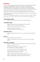
POWER
Your NVR will has an internal power supply that powers
the system as well as its built-in POE block. Do not modify
the power cord in any way or you may damage both the
recorder and any attached cameras.
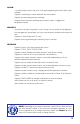
NETWORK PORT
Use this single Ethernet port to connect your NVR to your
network router. Do not connect a camera to this port.
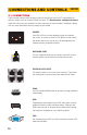
VIDEO IN POE PORTS
This block of ports is for use by your cameras. These ports
will send power to your cameras and receive their video.
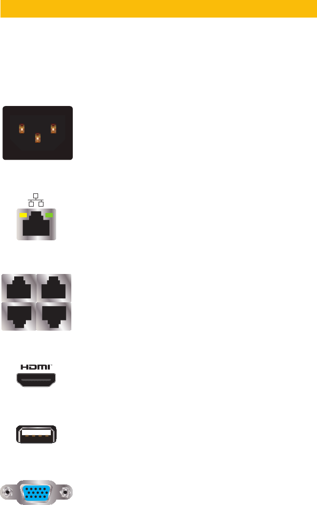
HDMI
Use the included HDMI cable to connect to a high-definition
video display.
USB
Depending on the model of your NVR, these ports may be
located on both the front and back panels. Connect your
USB mouse to one of the ports on the back panel, leaving
the other port available for use in backing up files.
VGA
For connecting your NVR to a VGA computer monitor. VGA
cable not included.