
Installation Guide

Rev 1.1
Page 2 of 3
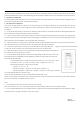
Fig. 3 Connection Wires of IT-RFHUB-01
Input wires:
Black: Line voltage, ACL
White: Neutral, CAN
Output wires:
Red: Low speed
Yellow: Medium speed
Blue: High speed
Installation
In-wall Switch:
The in-wall switch is a standard decora style wall switch which can be fitted into a standard wall box or onto a wall-
mount base plate that comes with the switch.
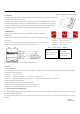
As shown in Fig. 1, remove the front panel of in-wall switch, then install 2 pcs of AAA batteries into the holders.
Please make sure the battery polarity is correct. All the LED lights on the in-wall switch will be on for 3 seconds
and then go out, which means the in-wall switch operates properly. Install the front panel back onto the switch.
If LED lights are not on after batteries are installed, please check the battery status and try again.
IT-RFHUB-01 Hub:
(Please switch off main power before wiring. The installation should be done by qualified
personnel only)
The hub (with a curved bottom) should be attached to the cylindrical fan housing and is wired to
the fan motor.
Remove the screw that holds down the hub cover and flip it up. Once the cover is open, a three
digit dip switch is available for fan speed configuration, as shown in Fig. 2.
Once wiring is completed, close the hub cover and tighten the screw.
Operation
1. Power on the Hub:
Switch on power to the hub, the Power indicator on the hub will be on, and other three indicators will stay off. Press the “Test” button to change fan speed,
the fan will run in the following cycles:
1 speed fan: on -> off -> on -> off,
2 speed fan: high speed -> low speed -> off -> high speed -> low speed -> off
3 speed fan: high speed -> medium speed -> low speed -> off -> high speed -> medium speed -> low speed -> off
And, the Test indicator will blink as follows:
Low speed on: the speed LED will blink once every 2 seconds,
Medium speed on: the speed LED will blink twice every 2 seconds, and
High speed on: the speed LED will blink three times every 2 seconds.
2. Pairing the Hub with the In-Wall Switch:
2.1 Press and hold the “Pair” button, the “Pair” LED will be on for three seconds then turn off. All previous pairing info is removed (one hub can be paired
with 20 in-wall switches respectively).
2.2 Press the “Pair” button twice, the “Pair” LED will have one blink every second, and the hub is in paring mode (all the buttons on the hub are
disabled).
Fig. 1 Install Battery onto In—wall Switch
Fig. 2 Dip Switch for Fan Speed Configuration
1 speed fan: Dial 1 to "ON”; and
2 speed fan: Dial 2 to "ON”; and
3 speed fan: Dial 3 to "ON”