B10 SERIES BOILER B3-B9 Boiler Manual And Installation Instructions for Atmospheric Venting Please Read Instructions Carefully Save for Future Reference WARNING If the information in this manual is not followed exactly, a fire or explosion may result causing property damage, personal injury or loss of life.
Dear Customer: Thank you for buying a QHT BIASI B10 Series Boiler. The QHT BIASI B10 Series Boiler is a cast iron, oil or gas fired hot water boiler, using the famous BIASI B10 (3-pass) design. The boiler is light, compact, simple, rugged and engineered for maximum home heating efficiency. We realize that it is not possible to answer all questions about the VEGA B10-series boiler system in this manual.
TABLE OF CONTENTS QHT BIASI B10 Series Section Important Information & Warnings Page 4,5,6 General Information 1 7 Boiler Block Assembly & Explosion Diagram 2 8 Boiler Location 3 9 Installation of Boiler Trim Kit Components 4 10,11 Piping the Boiler 5 12 Intake Venting 6 13,14 Exhaust Venting 7 15 Common Exhaust Venting 7.1 15,16 Blocked Flue Switch 7.2 16 Gas Venting 7.3 17 8 18 Oil 8.1 19 Gas 8.
IMPORTANT INFORMATION Please read this page carefully. • ALL BOILERS MUST BE INSTALLED IN ACCORDANCE WITH NATIONAL, STATE AND LOCAL PLUMBING, HEATING AND ELECTRICAL CODES AND ORDINANCES, AS WELL AS THE REGULATIONS OF THE SERVING ELECTRICAL, WATER AND GAS UTILITIES. • All systems should be designed by competent contractors, and only persons knowledgeable in the layout and installation of heating systems should attempt the installation of any boiler.
WARNING Any appliance that burns natural gas, propane gas, fuel oil, or coal is capable of producing carbon monoxide (CO). Carbon Monoxide (CO) is a gas which is odorless, colorless and tasteless but is very toxic. CO is lighter than air and thus may travel throughout the building. BRIEF EXPOSURE TO HIGH CONCENTRATIONS OF CO, OR PROLONGED EXPOSURE TO LESSER AMOUNTS OF CO MAY RESULT IN CARBON MONOXIDE POISONING.
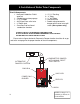
Homeowner Information for Gas TO START UP THE APPLIANCE 1. STOP! Read the safety information on the side of the boiler. DO NOT START THE BOILER UNLESS ALL CLEANOUT DOORS ARE SECURED AND SEALED. (Skip to step 9 for oil burning boilers) 2. Set thermostat to lowest setting 3. Turn off all electric power to the appliance 4. Do not attempt to light the burner by hand 5. Turn the manual shut off on the combination gas valve clockwise to the off position. 6. Wait five minutes to clear out any gas.
1. General Information The BIASI B 10-series boilers are wet base design, sectional, cast-iron boilers for forced hot water heating systems. The boilers are shipped pre-assembled from the factory in lengths from three to nine sections. They are designed for firing with oil or gas power burners, which are packed separately along with the jacket and controls for shipping purposes. When the boiler is received, check the contents to ensure that there is no shortage or damage to any part of the boiler system.
2. Boiler Block Assembly All QHT BIASI B10 Series Boilers are shipped from the factory in assembled boiler blocks. If, however, the block needs to be split into sections for ease of delivery, please read the following: To assemble split blocks, move sections into parallel and facing each other. Sections may be slid along boards placed underneath the sections. Inspect nipple ports for damage or burrs. Remove any burrs by scraping the port very lightly.
3. Boiler Location The following are the minimum clearance to construction or combustible materials: 9” 1. 9” from the top, sides, and rear of the boiler. 2. 18” from the flue pipe in any direction. 3. 24” from the front of the boiler. 24” 9” DANGER The boiler must be located on a non-combustible floor. A smooth, level concrete floor is recommended. Locate the boiler as close as possible to the chimney.
4.
4. Installation of Boiler Trim Components Cont. 1. Install L4006A aquastat in upper left or right rear tapping using 3/4” immersion well. All tapings and joints should be sealed with piping compound. The L4006A can be adjusted up to 220o F, and should be set to the desired temperature by the installer. The differential is also adjustable between 5 and 30 degrees. It should be set as close to 30 degrees as possible to prevent short cycling of the boiler.
5. Piping the Boiler All piping must conform to state and local codes. Page 11 shows the location and size of the boiler tappings. It is recommended to install unions and gate valves at the inlet and outlet of the boiler, so it may be readily isolated for service. For Canadian installations, a low water cut off is required if the boiler is installed above the level of radiation. Even if the boiler is installed below the level of radiation it is strongly recommended that a low water cut off be installed.
6. Intake Venting 1. Be certain adequate air is available for combustion and ventilation. a.) Boiler located in unconfined space: Installation in large areas, such as basements, can usually be assumed to provide sufficient air. b.) Boiler located in confined space : (See Figure A.
6. Intake Venting Cont. c.) Boiler located in a room under negative pressure: If the boiler is to be installed within a home where the operation of exhaust fans, attic fans, kitchen ventilation systems, clothes dryers or fireplaces may create severe negative vent pressures causing unsatisfactory combustion and venting, special provisions should be made for additional make-up air to supply the other air requirements.
7. Exhaust Venting The B10 boiler is a high efficiency unit that requires proper venting. The boiler must be vented to the outdoors by means of a tile lined masonry or a approved pre-fabricated chimney of the size and height recommended by the manufacturer or by a listed "power venting" unit which provides draft by mechanical means. In many installations, particularly older interior and most exterior chimneys, a corrosion resistant liner should be installed and may be required by code.
7.1 Common Exhaust Venting Cont. 3.Insofar as practical, close all building doors and windows and all doors between the space in which the appliance remaining connected to the common venting system is located and other spaces of the building . Turn on any appliance not connected to the common vent system. Turn on all exhaust fans except for summer exhaust fans. Close the fireplace damper if applicable. 4.Place in operation the appliance being inspected. Follow the lighting instructions.
7.3 Gas Venting For boilers connected to gas vents or chimneys, vent installations shall be in accordance with part 7, Venting of Equipment, of the National Fuel Gas Code, ANSI Z223.1 or Section 7, Venting Systems and Air Supply for Appliances, of the CAN/ CGA B149, Installation Codes, or applicable provisions of the local building codes. Vent connectors serving appliances vented by natural draft shall not be connected into any portion of mechanical draft systems operating under positive pressure.
8. Burner Setup Good, reliable operation with a minimum of service, starts with attention to the small details: Oil: 1. Setting the nozzle position and electrodes "by the book" using the manufacturer's gauges. 2. Installing a quality micron filter at the burner. 3. Making careful/tight flare connections, without couplings, on oil suction line. 4. Checking fuel pump pressure. 5. Checking draft at the breeching to insure it is adequate to overcome flue gas resistance. (-.02 to –.04 in. w.c.) 6.
8.1 Oil Burner Setup This page is only for boilers using an oil burner. If a gas burner is being used, please refer to page 19 for the proper setup of the burner and gas lines. BURNER MANUFACTURER: Boiler Model Burner Model Firing Rate Insertion Depth Nozzle Spray Pattern Pump Pressure Head Type Head Position B-3 NEC-1102* 0.55 3.50" 0.50 X 60 hollow 180 psi NX70LC 0.
8.2 Gas Burner Setup This page is only for boilers using a gas burner. If an oil burner is being used, please refer to page 18 for the proper setup of the burner. Natural Gas Riello Boiler Model Burner Model B-4 Propane R200 Input (MBH) 110 Man. Pres. (W.C.) 1.06” Head Setting 2.2 Air Gate 1 Man. Pres. (W.C.) 1.32” Head Setting 2 Air Gate 1 B-5 R200 140 1.20” 2.8 2 1.76” 2.7 2 B-6 R200 175 1.46” 2.8 3 2.34” 2.9 3 B-7 R400 207 1.22” 2 0 1.48” 2 0 B-8 R400 248 1.
9. Gas Line Piping Gas supply piping is to be sized and installed properly in order to provide a supply of gas sufficient to meet the maximum demand without undue loss of pressure between the meter and the boiler. Consult with the National Fuel Gas Code ANSI Z223.1 for proper sizing of gas piping for various lengths and diameters. Locate a drop pipe adjacent to, but not in front of the boiler. Locate a tee in the drop pipe at the same elevation as the gas inlet connection to the boiler.
10. Boiler Jacket Assembly NOTE: All piping, boiler controls, gauges and valves should be installed before the jacket is assembled on the boiler. Below is an explosion view of the boiler and jacket assembly to clarify these boiler jacket assembly instructions. Insert the separate (loose) piece of insulation on top of boiler with the foil side facing in so the entire top, bottom and sides of boiler are covered.
11. Wiring The electricity to the boiler shall come from a dedicated breaker in the electric service box. A service switch should be mounted on the side of the boiler so the burner technician can service the burner and controls. The electrical wiring should be routed so as not to interfere with normal servicing of the boiler.
11. Wiring 4006A WIRING 7248U WIRING 7248U WIRING PROCEDURE If you received a Honeywell 7248U with your Biasi boiler, you will need to make the changes shown above, and described below to the wiring diagrams. 1. 2. 3. 4. Run wire 1 to the L1 terminal on the 7248U instead of running wire 1 to the 4006A. Run wire 2 to the L2 terminal on the 7248U instead of connecting to wire 4. Run wire 4 to the B2 terminal on the 7248U instead of connecting to wire 2.
11. Oil Burner Wiring RIELLO OIL BURNER, CS HEATMANAGER, 7248U CONTROL WIRING RED YELLOW BROWN WHITE BLACK HONEYWELL 7248U NOTE: All wiring must be done in accordance with applicable state, local and national codes. Use only copper conductors.
Page 26 NOTE: All wiring must be done in accordance with applicable state, local and national codes. Use only copper conductors.
RIELLO OIL BURNER, AZ-4P, CONTROL WIRING WITH DHW PRIORITY NOTE: All wiring must be done in accordance with applicable state, local and national codes. Use only copper conductors.
Page 28 NOTE: All wiring must be done in accordance with applicable state, local and national codes. Use only copper conductors.
BECKETT NO/AFII OIL BURNER, ARM-4P, CONTROL WIRING WITH DHW PRIORITY NOTE: All wiring must be done in accordance with applicable state, local and national codes. Use only copper conductors.
Note 2: All wiring must be done in accordance with applicable state, local and national codes. Use only copper conductors. HEATWISE SU-2A, SR503, CONTROL WIRING WITH DHW PRIORITY 11.
RIELLO GAS BURNER, AR861-2II,CONTROL WIRING WITH DHW PRIORITY NOTE: All wiring must be done in accordance with applicable state, local and national codes. Use only copper conductors.
12. Commissioning Before a gas boiler may be put into operation and tested, it’s gas connection must be leak tested. After installation of oil/gas-fired boiler, operation and performance tests shall be conducted to make certain that the burner is operating in an acceptable manner and that all safety controls and devices function properly. It is critical that the high limit, low water cutoff and burner "cad cell" relay be checked for normal operation before leaving the job.
14. Installer Notes System Checkout: Boiler Model No._________________ Serial No.__________ Original Purchaser: _________________________ Installer: ______________________ _________________________ ______________________ _________________________ ______________________ Burner Manufacturer----------- Type of Oil Burner------------- Burner Model No.-------------- Burner Serial No.-------------- Nozzle Manufacturer------------- Nozzle Spray Angle------------ G.P.H.
Page 34
Page 35
Warrantyfor BIASI - B10 Residential Cast-Iron Water Boilers FIRST YEAR-WARRANTY FOR B10 SERIES RESIDENTIAL HOT Portsmouth, NH, freight pre-paid. WATER BOILERS: QHT warrants that its cast-iron boiler and casing are free from defects in material and workmanship for one year from QHT and Biasi will not be responsible for: the date of installation. If the boiler is found to be defective within 1. Components that are part of the heating system, but this period, QHT will replace the boiler block or casing.