Non-Condensing Vent Component & Installation Guide Riva HEAT ONLY & COMBI BOILER Please Read This Guide Carefully and Save for Future Reference - This guide is intended to provide detailed information regarding venting components and installation. - This guide must be used in conjunction with the boiler installation manual. Prepared by: QHT, Inc. Portsmouth, NH 603-334-6400 phone www.qhtinc.com Rev. B 04.08.
Table of Contents: Restrictor Sizing Chart …………………...…………………………………. 4 External Vent Warnings ………………………………………………………. 4 External Vent Clearances ……………………………………………………. 5 Concentric Riser Kit - RI VC RIS 9990322 …………………………………. 6 Concentric Riser Kit Installation Instructions ………………………………. 7-9 Standard Concentric Kit - RI VC 9990148 …………………………………. 10 Standard Concentric Kit Installation Instructions ………………………….. 11-12 Concentric Vent Accessories ………………………………………………...
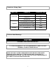
Restrictor Sizing Chart Vent Type Length (ft) Restrictor Size 1.65 to 3.3 41 3.3 to 8.8 44 8.8 to 32.8 None 1.65 (in) and 1.65 (out) 38 3.3 to 39.40 (tot. in + out) 41 39.40 to 131 (tot. in + out) None 3.3 to 27.8 None Concentric Separate Vertical Exterior Vent Warnings CAUTION EXTERNAL VENT SURFACES ARE HOT. IT IS THE RESPONSIBILITY OF THE HOMEOWNER TO KEEP THE VENT TERMINAL CLEAR OF SNOW AND ICE. NOTE: USE ONLY LISTED COMPONENTS SUPPLIED WITH THE BOILER.
Exterior Vent Clearances The Exhaust Hood should be installed on the leeward side of the house and conform to the following guidelines: 1. The vent hood shall not be less than 3 feet above any forced air inlet to the house. 2. The vent hood shall not be less than 1 foot below, 1 foot horizontally, or 1 foot above any door, window or gravity inlet into any building. 3. The vent hood shall not be less than 2 feet from an adjacent building. 4.
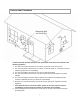
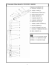
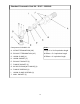
Concentric Riser Vent Kit - RI VC RIS - 9990322 Components included in kit: A. EXHAUST GASKET (4) B. UNION CLAMP (3) C. RISE EXHAUST PIPE (18”) D. RISE INTAKE PIPE (20”) E. UNION GASKET (3) F. FLANGE GASKET (1) G. FLANGE SCREWS (4) H. BOILER COLLAR (1) I. UNION CLAMP SCREWS (6) J. 90 DEG ELBOW (1) K. INTAKE TERMINATION (38”) L. EXHAUST TERMINATION (40”) M. WALL GASKET (2) Notes: Length 1’ to 32.8’ equivalent length 90 Elbow = 5.
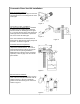
Concentric Riser Vent Kit Installation Pipe connections (Figure 1): Whenever joining concentric pipe cut the inner exhaust pipe so it is 1 inch long than the outer intake pipe. Figure 1 Termination Location / Installation: The concentric termination piece is installed by sliding the outer intake pipe through the wall from inside the building (shown in figure 2). The inner exhaust pipe is then slid into the intake pipe until the termination cap bottoms out on the end of the intake pipe.
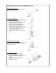
Concentric Riser Vent Kit Installation Cont. Intake Gasket Installation : Install the intake gaskets (E) on the intake pipes as shown in Figure 6. Figure 6 Vertical Rise Installation : • Install the flange gasket (F) onto the boiler outlet as shown in Figure 7. • Attach the boiler collar (H) to the outlet of the boiler using the 4 screws (G). • Insert the vertical exhaust pipe (C) into the boiler collar.
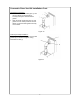
Concentric Riser Vent Kit Installation Cont. Termination Connection : • Slide the exhaust termination pipe (L) into the riser elbow (J) until the pipe is securely held by the internal exhaust gasket • Slide the intake termination pipe (K) and gasket over the intake portion of the riser elbow (J) until the intake gasket fits firmly on the elbow.
Standard Concentric Vent Kit - RI VC - 9990148 Components included in kit: Notes: A. INTAKE TERMINATION (38”) Length 1’ to 32.8’ equivalent length B. EXHAUST TERMINATION (40”) 90 Elbow = 5.4’ equivalent length C. UNION CLAMP (1) 45 Elbow = 3’ equivalent length D. UNION GASKET (1) E. EXHAUST GASKET (2) F. FLANGE GASKET (1) G. 90 DEG ELBOW (W/ FLANGE) (1) H. FLANGE SCREWS (4) I. UNION CLAMP SCREWS (6) J.
Standard Concentric Vent Kit Installation Pipe connections (Figure 1): Whenever joining concentric pipe cut the inner exhaust pipe so it is 1 inch long than the outer intake pipe. Figure 1 Termination Location / Installation: The concentric termination piece is installed by sliding the outer intake pipe through the wall from inside the building (shown in figure 2). The inner exhaust pipe is then slid into the intake pipe until the termination cap bottoms out on the end of the intake pipe.
Standard Concentric Vent Kit Installation Cont. Termination Installation : • Install the wall gaskets (J) on the termination pipe (A). One gasket from the inside of the wall and one from the outside. • Install the intake gasket (D) on the termination pipe (A) Figure 6 Elbow Installation : • Install the flange gasket (F) onto the boiler outlet as shown in Figure 7. • Attach the boiler elbow (G) to the outlet of the boiler using the 4 screws (H). • Insert the termination exhaust pipe into the elbow.
Concentric Vent Accessories Concentric Extension - RI VC EXT - 9990149 Equivalent Length: 3.3’ Components included in kit: A. UNION CLAMP (1) B. UNION GASKET (1) C. INTAKE PIPE (38”) D. EXHAUST GASKET (1) E. EXHAUST PIPE (40”) F. EXHAUST PIPE CENTERING BRACKET (4) G. UNION CLAMP SCREWS (2) Concentric 90 Degree Elbow - RI VC 90 - 9990152 Components included in kit: A. UNION CLAMP (1) B. UNION GASKET (1) C. EXHAUST GASKET (1) D. 90 DEG ELBOW MALE X FEM. (1) E. UNION CLAMP SCREWS (2) Equivalent Length: 5.
Separate Vent Kit - RI VS - 8990016 Components included in kit: A. EXHAUST TERMINATION (1) B. TERMINATION SCREW (2) C. WALL GASKET (4) D. EXHAUST PIPE (39”) E. EXHAUST / INTAKE GASKET (4) F. 90 DEG ELBOW MALE X FEM. (2) G. FLANGE SCREWS (4) H. INTAKE PIPE (1) I. INTAKE COLLAR (1) J. EXHAUST COLLAR (1) K. FLANGE GASKET (1) L. EXHAUST RESTRICTOR (SUPPLIED WITH BOILER) M. INTAKE TERMINATION (1) Notes: Maximum length 131’ equivalent length 90 Elbow = 5.
Separate Vent Kit Installation Termination Location / Installation: Drill the intake and exhaust holes through the external wall according to the boiler mounting diagram supplied in the boiler package. Be sure to account for the 3° downward pitch away from the boiler as shown in Figure 1. 3° Downward pitch (2” per 39” length). Away from boiler Figure 1 Gasket Installation: Install the gaskets (E) in the exhaust and intake boiler collars (I,J) and elbows (F), as shown in figure 2.
Separate Vent Kit Installation Cont. Intake Installation : Remove the intake cover plate. Install the intake gasket over the intake hole. Mount the intake collar (I) with the 4 screws (G) supplied, as shown in figure 5. Figure 5 Elbow Installation : Figure 6 • Install the exhaust elbow (F) onto the exhaust collar (J). • Install the intake elbow (F) onto the intake collar (I). • Slide each termination (intake & exhaust) into the corresponding elbow.
Separate Vent Accessories Separate Extension - RI VS EXT - 9990159 Equivalent Length: 3.3’ Components included in kit: A. INTAKE / EXHAUST EXTENSION (39”) B. INTAKE / EXHAUST GASKET (1) Separate 90 Degree F X F Elbow - RI VS 90F - 9990160 Components included in kit: A. 90 DEGREE FEM. X FEM. ELBOW (1) B. INTAKE / EXHAUST GASKET (1) Equivalent Length: 5.4’ Separate 45 Degree Elbow- RI VS 45 - 9990162 Components included in kit: A. 45 DEGREE MALE X FEM. ELBOW (1) B.
Vertical Roof Vent Kit - RI RV - 9990251 Components included in kit: Notes: A. ROOF FLASHING - FLAT / PITCHED* (1) • Maximum height 27.8’ equivalent length B. EXTERIOR TERMINATION (1) C. TERMINATION FLANGE (1) • 90 Elbow = 3.3’ equivalent length D. TERMINATION MOUNTING SCREW (3) • 45 Elbow = 1.6’ equivalent length E. EXHAUST ADAPTER GASKET (1) • Maximum 4 elbows (45 or 90) F. EXHAUST ADAPTER (1) • When equivalent height is greater G. INTAKE ADAPTER (1) than 9.8’ a condensate collector H.
Vertical Roof Vent Kit Installation Termination Location / Installation: Figure 1 Before installing the roof termination, ensure the proposed location meets the clearance requirements in the boiler installation manual and any local code requirements. Figure 1 Standard Roof Vent Height: The standard roof vent kit is 53.5 inches from the top of boiler to the top of the termination. Extensions and elbows can be added, as needed. These parts are shown on page ?.
Vertical Roof Vent Kit Installation Cont. Gasket Installation : Insert the gaskets (E,H,I) into the corresponding adapters as shown in figure 5. Be sure to install the gaskets so the bevels of the gasket are oriented as shown. Figure 5 Boiler Collar Installation : Figure 6 • Install the intake gasket (L) onto the flue outlet of the boiler. • Attach the boiler collar (J) to the boiler using the 4 screws (K). • Slide the adapters (F, G) into the collar (J). Be sure not to damage the gaskets.
Vertical Roof Vent Accessories Vertical Roof Vent Extension - RI RV EXT - 9990242 Components included in kit: Equivalent Length: 3.3’ A. INTAKE EXTENSION (39”) B. EXHAUST GASKET (1) C. INTAKE GASKET (1) D. EXHAUST EXTENSION (39”) E. CENTERING BRACKET (1) Vertical Roof Vent 90 Degree Elbow - RI RV 90 - 9990256 Equivalent Length: 3.3’ Components included in kit: A B A. EXHAUST PIPE (1) B. INTAKE PIPE (1) C. INTAKE GASKET (1) C D.
Vertical Roof Vent Accessories Cont. Vertical Roof Vent Condensate Siphon - RI RV CS - 9990276.1 Note: Must be used with the condensate collector when the total equivalent height is greater than 9.