
User's Manual


2.2 Description of parts
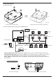
3.
4.
1.
2.
5
H-NET
WLAN
SYS
POWER
Power status LED: red
lights up when power on.
Reset
2.3 General data
6
7
8
9
10
Interfaces
Power adapter interface
Internet access
485 commu. terminal
H-NET commu. terminal
Backup power supply terminal
Connection
connect to power source of DC12V/1A
connect to LAN port of router
connect to 485 commu. port of electric meter
(1) WiFi Reconfiguration:
Insert and press the reset
button for over 3s (no more
than 10s). Meanwhile, the
WLAN status LED flashes.
The WiFi module is restored
to factory settings. The
hotspot of HIS-XXXX
appears after about 10s. The
XXXX is the last four
characters of the WiFi ID.
(2) Reset to factory setting:
Insert and press the reset
button for over 10 seconds.
Meanwhile, the system
status LED flashes. The
whole system is restored to
factory settings.
connect to power adapter in accessories
connect to commu. bus of outdoor/indoor unit
Top cover
Bottom cover
The third party power source is allowable only when AC plug failed to comply
with local regulations. Port 6 and 10 shall not be used simultaneously as the DC
power input in case of power failure.
System status LED: green
flashes at every 1s.
8
9
10
6
7
Base
WLAN status LED: blue
lights up when connecting into network successfully.
H-NET commu. LED: yellow
flashes when communicating.
3
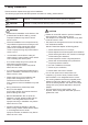
CAUTION
Parameter
91x117x31 (mm)
0.14kg
Indoor
<5km (if a low altitude AC adapter is connected in, please refer to its manual)
maximum 64
0℃~40℃
30%RH~60%RH
2.4W
100-240V~50/60Hz
Item
Outer dimension (WxHxD)
Net weight
Installation location
Altitude
Quantity of connected indoor units
Ambient temperature
Ambient humidty
Power
Input power of power adapter