
Installation guide

1–Installation
Bringing Up the System For the First Time
1-36 D000102-000 B
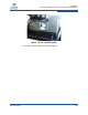
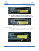
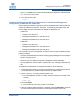
2. Peel off the protective label. Re-engage the lever and tighten the thumb
screw as shown in Figure 1-35.
Figure 1-35 MRL Protective Label 6
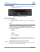
Start-up Procedures
1. Power up the switch.
2. From its flash image on the management module, the switch begins its boot
process.
NOTE:
If the DB9 port of the SEEB module or the RS232 port on the 12200/12300 is
connected to a terminal emulation program, the user will be able to view the
switch boot process. Be certain to use a null-modem/crossover serial cable
for the console port. For users assembling their own cable, refer to
Appendix C for serial port pinout information. The settings for the terminal
emulation device should be:
•8 data bits
•no parity bits
• 1 stop bit
• 57.6K baud
• Use VT100 emulation.
• Flow control = XON/XOFF
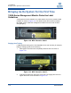
3. Verify the IP address with the command line interface (CLI) command
showChassisIpAddr command. The system returns the information similar
to the following:
Chassis IP Address: 192.168.100.9 Net mask: 255.255.240.0
Changing the Switch IP Address and Default Gateway via the CLI
The command line interface (CLI) can be accessed via Telnet, SSH, the SEEB
module DB-9 or 12200/12300 RS-232 serial port(s).