
Installation guide

1–Installation
Bringing Up the System For the First Time
D000140-001 D 1-51
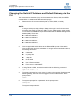
2. Peel off the protective label. Re-engage the lever and tighten the thumb
screw as shown in Figure 1-47.
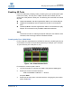
Figure 1-47. MRL Protective Label 6
Start-up Procedures
1. Power up the switch.
2. From its flash image on the management module, the switch begins its boot
process.
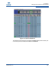
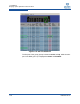
3. Verify the IP address with the command line interface (CLI) command
showChassisIpAddr command. The system returns information similar to
the following:
Chassis IP Address: 192.168.100.9 Net mask:
255.255.240.0
NOTE:
If the DB9 port of the SEEB module or the RS232 port on the 12200/12300
is connected to a terminal emulation program, the user will be able to view
the switch boot process. Be certain to use a null-modem/crossover serial
cable for the console port. For users assembling their own cable, refer to
Appendix C for serial port pinout information. The settings for the terminal
emulation device should be:
8 data bits
no parity bits
1 stop bit
57.6K baud
Use VT100 emulation.
Flow control = XON/XOFF