
User`s manual


Table Of Contents
- Preface
- General Description
- Installation
- Introduction
- Unpack
- Place or Mount the Equipment
- Apply the IEC Class 1 Laser Information Label (If the installation is in Europe)
- Install GBICs
- Connect to AC Power
- Switch Logic Power Good LED
- Check the Power-On-Self-Test (POST) Results
- Cable Fibre Channel Devices to the Switch
- Configure the Chassis
- Configure the Ports
- Zoning
- Rack and Shelf Administration
- Operating the Switch
- Diagnostics/Troubleshooting
- Removal/Replacement Procedures
- Multi-Chassis Fabrics
- Reference Information
- QLogic Customer Support
- Index
Preliminary
Input Fuse
SANbox-16HA Fibre Channel Switch
4-2 Removal/Replacement Procedures 59005-03 Rev. A Installer’s/User’s Manual
Replacement
1. Insert the Fuse into the Fuse Holder. Refer to Appendix A Reference Infor-
mation for fuse-type information.
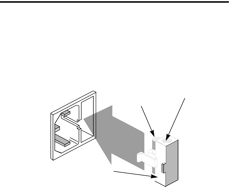
2. Refer to Figure 4-2. Insert the Fuse Holder into the right side of the AC
Power Plug Assembly and press it in until it clicks flush with the front surface
of the assembly.
3. Plug the AC Power Cable into the AC Power Plug Assembly.
4. Press the Power Switch to the ON position.
Figure 4-2 Fuse Replacement
Fuse
4 AMP, 250V
Spare Fuse
Fuse Holder