
Install Instructions


2. Drill hole in wall (or floor) at desired location for power supply
entry. Install power supply wiring to heater and thermostat
location as determined by thermostat option selected. Allow
approximately 10 to 12in(254mm to 305mm) of wire at heater
for connections.
3. If any other Marley accessories are to be used with this
heater, refer to installation instructions provided with the
accessory for proper installation and wiring.
4. Wireway Cover - Commercial Baseboard Only
a. The wireway cover is a factory installed feature of Marley
commercial baseboard heaters. Two cables or four indi-
vidual conductors plus two ground wires may be routed
through the wireway. Refer to page 2 for maximum cur-
rent loads.
b. To gain access to wireway, lay heater face down and
remove two screws as shown in Figure 4. Remove the
knockouts in the channel areas of both terminal boxes.
c. Insert the plastic bushings from the parts kit (in wiring
compartment) in the knockout holes.
d. Wire heater according to Figure 5. Reattach the wireway
cover using the two screws.
5. Loosen screw in built-in cable clamp or remove
desired knockout from heater wiring compartment (Figures
3 and 4). Install power cable into wiring compartment allow-
ing at least 6in(153mm) of cable for connection to heater.
To install two power cables using the built-in cable clamp,
bend tab covering second hole up and back to rear wall of
wiring compartment. If built-in cable clamp is not used,
install approved cable connector (not included ) in desired
knockout.
6. Position heater to wall (use cross stamped perforations as
a guide, see Figure 4) and secure through the top row of
predrilled mounting holes using at least two fasteners, one at
each end of the heater. If the unit is mounted above the floor
to allow carpet installation under the heater, two additional
mounting holes are supplied at each end below the element.
This will allow you to screw into the sill plate if the unit does
not span across two wall studs.
To prevent a possible fire, make sure all wire connections are
tight.
WARNING
!
CAUTION
!
Figure 4.
Figure 5.
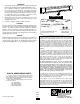
Figure 6. Typical Thermostats
3
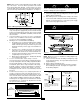
NOTE: Make sure the caution label with the word “TOP” is at the
top of the heater. For most efficient operation locate heaters
along outside wall under windows. Position heater so it can be
secured to wall stud. Power cable must enter heater through one
of the knockouts provided in wiring compartment. See Figure 3.
NOTE: When accessories are installed, use wiring diagram sup-
plied with the accessory.
9. If front cover was removed, reinstall by hooking the top edge
on the support bracket(s). Then push down to latch onto the
support bracket(s).
10. Replace wiring compartment cover.
11. Follow instructions accompanying thermostat for installa-
tion and wiring thermostat. See Figure 6 for typical ther-
mostat wiring diagrams.
7. Connect the supply cable grounding wire to the bare copper
pigtail in wiring compartment.
8. After making sure the electrical power coming to the heater
is turned off at main switch panel follow the desired wiring
diagram, as shown in Figure 5, to connect the power supply
to the heater using approved wire nuts.
BOTTOM
MOUNTING HOLES
When using bottom mounting holes, (to prevent a possible
shock or fire hazard,) make sure you do not drive the screws
through or damage the power supply wire.
TOP
MOUNTING
PERFORATIONS
Double Line Break
Thermostat
L2 L1
Breaks in
“OFF”
position
Breaks on temp.
rise and in
“OFF” position
Double line break thermostats have
an “OFF” switch that is open only
when the thermostat is put in the
“OFF” position
To heater
Power
supply
Single Line Break
Thermostat
L2
L1
(HOT)
Breaks on
temp. rise
Single line break thermostats DO NOT
have an “OFF” position and will operate
at a temperature below its minimum set point
To heater
Power
supply
(1
Figure. 3 Wiring Compartment Dimensions
6.75
(153,2)