
Manual


Rough-in Wiring
1. Branch circuits for the heaters shall be enclosed in 1” rigid
conduit for 05A heaters, or 1-1/4” rigid conduit for 07A
heaters.
2. Run branch circuit of proper voltage and wire size, in rigid
conduit, to location of left or right junction box as indicated
on heater wiring diagram. Wire entry to heater is through
either end pedestal.
Note
When pedestal is not used for wire entry, pedestal base
must be covered with cover plate (supplied with pedestal). See
Figure 2.
3. When installing heaters on existing floors, the threaded end
of the rigid conduit must extend 7/8” to 1” above finished
concrete. Conduit must be threaded a minimum of 3/8”.
4. Basic heaters are prewired and can be connected to branch
circuit at either end. Heaters with controls are prewired for
connection to branch circuit at one end only (refer to heater
wiring diagram), however, heater can be wired from opposite
end by running wires through heater wireway.
5. If it is necessary to run wires through the heater wire way,
use Table B to size the field installed wiring.
6. The factory installed wires in the heater wireway can be
loaded up to 35 amps in 05A units and up to 45 amps in 07A
units. Refer to Table C and D for maximum length of heater
run when the heaters are connected in parallel.
Thermostat
24 amps @ 120-240 VAC
22 amps @ 277 VAC
Pilot duty– 125 VAC (all voltages)
Transformer relay
05A units: 22 amps @ 120-240 VAC
19 amps @ 277 VAC
07A Units: 25 AMPS @ 120-240 VAC
22 AMPS @ 277 VAC
Power relay
25 amps @ 120-277 VAC- see wiring dia-
gram on heater
Disconnect switch
20 amps @ 120-277 VAC
7. Standard 75˚C wiring must be used in junction boxes,
wire-
way and blank sections.
Room Layout
Refer to heating plans for exact room arrangements of heaters
(with or without thermostat and/or relays and/or switches and
accessories.)
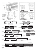
Mounting Height
Refer to Figure 1a. for typical mounting of heaters and pedestals
imbedded in floor; refer to Figure 1b. for surface-mounted
heaters and pedestals.
Note:
Up to 3/4” thick floor covering, such as carpet, tiles,
linoleum, etc., may be installed around and under the heater.
IF THE FACTORY INSTALLED WIRES IN THE WIREWAY
ARE USED TO CONNECT THE BUILT-IN CONTROLS, LIMIT
THE MAXIMUM CURRENT TO THE VALUES LISTED
3
Maximum allowable current
Copper Maximum no.
wire size of wires Up to 3 4 to 6 7 thru 9
75º C in wireway Conductors Conductors Conductors
No. 12 AWG 9 11.5 amps 9.3 amps 8.1 amps
No. 10 AWG 8 17.4 amps 14.0 amps 12.1 amps
No. 8 AWG 4 24.0 amps 21.0 amps –
Table B. Sizing Field Installed Wiring
Watts/Ft. of Maximum allowable length of heater run (feet)
the heaters 120 Volts 208 Volts 240 Volts 277 Volts
125 33 58 67 77
188 22 38 44 51
250 16 29 33 38
Table C. Maximum Length of Heater Run
(05A-1Ø)
Note:
For mix of watt densities, calculate amp draw. Do not
exceed values indicated in step 6 above.
TABLE D. Maximum Length of Heater Run
(07A - 1Ø and 3Ø)
Watts/Ft. of Maximum Allowable Length of Heater Run (Feet)
the Heaters 208 Volts 208 Volts 240 Volts 240 Volts 277 Volts
1Ø 3Ø 1Ø` 3Ø 1Ø
125 74 - 86 - 99
188 49 - 57 - 66
250 37 - 43 - 49
376 24 - 28 - 33
500 18 - 21 - 24
564 16 27 19 32 22
625 14 24 17 29 19
750 12 20 14 24 16
Heater Capacity
(Watts.Ft. Heater Length)
125, 188 and 250 Watts/Ft.
376, 500, 564, 625 and 750
Watts/Ft.
Heater
Dimension “A”
(Minimum Mounting
Height Above Floor)
1-3/4”
3”
Pedestal
Dimension “B”
(Minimum Height
Above Floor)
2”
3-1/4”
Leveling
Nut
Locknut (Do
Not Loosen
Or Remove)
Floor
Line
Pedestal
Locknut
Welded
Bracket
Heater
2-7/8” (5” Heaters)
4-1/8” (7” Heaters)
3/8”
Figure 1a. Pedestal Imbedded in Floor
Welded
Bracket
Locknut
Leveling
Nut
Locknut (Do
Not Loosen
Or Remove)
Floor
Line
A
A
B
Heater
Pedestal
Base Mounting
Holes - 1/4” DIa.
(Suitable
Fasteners By
Others)
Rigid
Conduit
Figure 1b. Surface-Mounted Pedestal
Heater Catalog Number Height Above Floor (Dim. “A)
Min. Max.
05A 2-5/8” 3-3/8”
07A 3-7/8” 4-5/8”