
Manual

DO NOT MOUNT MERCURY TYPE THERMOSTAT DIRECTLY
ON UNIT. VIBRATION COULD CAUSE HEATER TO
MALFUNCTION.
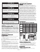
MANUAL RESET LIMIT
(FACTORY INSTALLED OPTION
ONLY.) THE LIMIT SWITCH IS LOCATED INTERNALLY ON
THE REAR OF THE HEATER. ON THE 3KW AND 5KW
MODELS, THE ACCESS TO THE RESET BUTTON IS ON THE
RIGHT SIDE (WHEN FACING REAR OF HEATER); ON ALL
OTHER MODELS IT IS NEAR THE TOP REAR OF THE
HEATER.
THE MANUAL RESET LIMIT IS IN SERIES WITH THE AUTO-
MATIC RECYCLING PROTECTOR (LIMIT). THE MANUAL
RESET LIMIT WILL NOT RESET UNTIL THE HEATER HAS
COOLED AND THE BUTTON IS PUSHED IN.
HEATER LOCATION INSTRUCTIONS
Arrange units so their discharge air streams:
a.
are subjected to a minimum of interference from columns,
machinery and partitions;
b.
wipe exposed walls without blowing directly at them;
c.
are directed away from room occupants in comfort heating;
d.
are directed along the windward side when installed in a
building exposed to a prevailing wind.
Locate thermostats approximately 5' (1524mm) above the floor
on interior partition walls or post away from cold drafts, internal
heat sources and away from heater discharge air streams.
Small rooms can be heated by one unit heater.
Large rooms require multi-unit installations. Number and capaci-
ty of units will be determined by volume of building and square
feet of floor area to be heated. Arrange units to provide perime-
ter air circulation where each unit supports the air stream from
another.
MOUNTING THE HEATER - GENERAL
The heater may be mounted to discharge the heated air either
horizontally or vertically. When the heater is mounted for vertical
discharge, it is recommended that the heater be positioned so
that the access door will open away from the wall to provide
greater access to the wiring and control compartment. If the
heater is to be mounted with the access door facing a wall, the
heater must be mounted far enough from that wall to allow full
opening of the access door (a distance approximately equal to
the width of the heater ... check clearance before installing).
Refer to Table 1 for wall and ceiling clearances before mounting
heater.
The heater may be mounted for either vertical or horizontal dis-
charge by the use of threaded rods. (Refer to Table 2 for thread-
ed rod sizes required.) Observe the detailed procedures in the
following installation instructions.
The heater may also be suspended from the wall or ceiling by
means of an optional mounting bracket (type MMB or MCMB)
which permits horizontal pivoting of the heater.
After the heater is installed, the louvers may be positioned to
direct the heated air in the desired direction. When the heater is
installed for horizontal discharge, the louvers should direct the
air either straight ahead or downward. Directing the air upward
may cause the heated air to remain in the ceiling area and
waste energy.
TO PREVENT POSSIBLE OVERHEATING OR DAMAGE DUE
TO OVERHEATING, KEEP AT LEAST 5' (1524MM) CLEAR-
ANCE IN FRONT OF HEATER. REFER TO TABLE 1 FOR
SIDE, TOP, AND BACK CLEARANCE REQUIREMENTS.
ALL BUILT-IN THERMOSTATS: IF THE HEATER IS USED TO
PREVENT PIPING OR LIQUIDS FROM FREEZING, AND IF
THE THERMOSTAT IS SET BELOW 45° F (7°C), THE FAN
MUST RUN CONTINUOUSLY.
THE CEILING MOUNTING STRUCTURE AND THE ANCHOR-
ING PROVISIONS MUST BE OF SUFFICIENT STRENGTH
TO SUPPORT THE COMBINED WEIGHT OF THE HEATER
AND MOUNTING BRACKET. (SEE TABLE 4).
THE HEATER MUST BE MOUNTED AT LEAST 7' (2134MM)
ABOVE THE FLOOR TO PREVENT ACCIDENTAL CONTACT
WITH THE FAN BLADE WHICH COULD CAUSE INJURY.
2
A
B
C
D
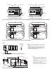
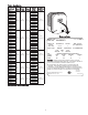
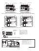
Figure 1. Horizontal Discharge Mounting and Spacing.
CEILING
BACK WALL
B
A
C
K
W
A
L
L
S
I
D
E
W
A
L
L
MOUNTING
ROD
LOCK NUT
UNIT HEATER
THREADED
MOUNTING
H
OLES
B
A
D
C
(TOP VIEW)
Table 2. Rod Thread and Spacing Dimensions, inches (mm)
for Horizontal Discharge
Rod Thread
Unit Type A B C D
3 - 5 kW
64
1
/
16
3
/
4
6
1
/
16
(152.4) (103.1) (19.0)
7.5 - 10 kW
5
/
16
- 18
(153.9)
15 - 20 kW
11
3
/
8
8
7
/
8
5
1
/
8
3
/
4
(289.0)
(225.6) (130.3) (19.0)
25 - 30 kW
10
9
/
16
14 - 12 6
3
/
16
5
/
8
(268.2) (368.3) (157.2) (16.0)
40 - 50 kW
3
/
8
- 16
15
15
/
16
14 - 12 6
3
/
16
5
/
8
(404.9) (368.3) (157.2) (16.0)
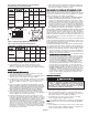
Table 1. Wall and Ceiling Clearance, inches (mm)
Unit Discharge Ceiling Side Wall Back Wall
3 & 5 kW
Horiz. 2 (50.8) 6 (152.4) 9 (228.6)
Vert. 6 (152.4) 18 (457.2) 18 (457.2)
7.5 to 10 kW
Horiz. 6 (152.4) 6 (152.4) 13 (330.2)
Vert. 6 (152.4) 24 (609.6) 24 (609.6)
15 to 10 kW
Horiz. 6 (152.4) 9 (228.6) 12
1
/
2
(317.5)
Vert 6 (152.4) 24 (609.6) 24 (609.6)
25 to 50 kW
Horiz. 16 (406.4) 12 (304.8) 18
1
/
2
(470.0)
Vert. 12 (304.8) 39 (914.4) 39 (914.4)