QNAP Turbo NAS Hardware User Manual © 2014. QNAP Systems, Inc. All Rights Reserved.
Thank you for choosing QNAP products! This user manual provides description of the hardware of the Turbo NAS and relevant guideline of certain functions. Please read carefully and strictly adhere to the instructions of the manual.
DISCLAIMER In no event shall QNAP Systems, Inc. (QNAP) liability exceed the price paid for the product from direct, indirect, special, incidental, or consequential damages resulting from the use of the product, its accompanying software, or its documentation.
Regulatory Notice FCC Notice QNAP NAS comply with different FCC compliance classes. Please refer the Appendix for details. Once the class of the device is determined, refer to the following corresponding statement. ======================================================= FCC Class A Notice This device complies with Part 15 of the FCC Rules. Operation is subject to the following two conditions: 1. This device may not cause harmful interference. 2.
FCC Class B Notice This device complies with Part 15 of the FCC Rules. Operation is subject to the following two conditions: 1. This device may not cause harmful interference. 2. This device must accept any interference received, including interference that may cause undesired operation. Note: This equipment has been tested and found to comply with the limits for a Class B digital device, pursuant to Part 15 of the FCC Rules.
Symbols in this document This icon indicates the instructions must be strictly followed. Warning Failure to do so could result in injury to human body or death. This icon indicates the action may lead to disk clearance or loss OR Caution failure to follow the instructions could result in data damage, disk damage, or product damage.
Table of Contents Table of Contents ............................................................................................... 7 Safety Warnings ................................................................................................. 8 Chapter 1. CPU and Memory Specifications ..................................................... 9 Chapter 2. Power Button and Reset Button Behavior .................................... 19 Chapter 3. USB One Touch Copy .......................................
Safety Warnings 1. The NAS can operate normally in the temperature of 0ºC–40ºC and relative humidity of 0%–95%. Please make sure the environment is well-ventilated. 2. The power cord and devices connected to the NAS must provide correct supply voltage (100W, 90–264V). 3. Do not place the NAS in direct sunlight or near chemicals. Make sure the temperature and humidity of the environment are in optimized level. 4. Unplug the power cord and all connected cables before cleaning.
Chapter 1. CPU and Memory Specifications Caution: Modifying the hardware, software, or firmware of the QNAP products will void the warranty. QNAP is not responsible for any form of damage or loss of data caused by modding the QNAP products. Users should bear their own risks of all sorts of possible data loss or system instabilities due to changing the hardware parts, modifying the default system firmware or installing any unauthorized third party applications on QNAP products.
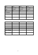
System TS-120 TS-220 TS-420 CPU Marvell 1.6GHz Marvell 1.6GHz Marvell 1.6GHz Memory 512MB DDR3 512MB DDR3 512MB DDR3 Flash 16MB 16MB 16MB CPU replaceable No No No Memory replaceable No No No 0 0 0 1 2 4 System TS-121 TS-221 TS-421 CPU Marvell 2.0GHz Marvell 2.0GHz Marvell 2.
System HS-210 CPU Marvell 1.6GHz Memory 512MB DDR3 Flash 16MB CPU replaceable No Memory replaceable No Number of SODIMM slots Number of hard drive slots 0 2 System TS-420U TS-421U CPU Marvell 1.6 GHz Marvell 2.
System TS-470 CPU Dual-core Intel® 2.6GHz Dual-core Intel® 2.6GHz Dual-core Intel® 2.
System CPU TS-470 Pro TS-670 Pro TS-870 Pro Dual-core Intel® Core™ Dual-core Intel® Core™ Dual-core Intel® Core™ i3 3.3 GHz i3 3.3 GHz i3 3.
System TS-1279U-RP TS-EC879U-RP TS-EC1279U-RP Dual-core Intel® Core™ Quad-core Intel® Quad-core Intel® i3 3.30 GHz Xeon™ 3.20 GHz Xeon™ 3.
System CPU Memory TS-269 Pro TS-469 Pro TS-569 Pro Dual-core Intel® Dual-core Intel® Dual-core Intel® Atom™ 2.13 GHz Atom™ 2.13 GHz Atom™ 2.
System CPU Memory TS-469U-RP/SP TS-869U-RP TS-1269U-RP Dual-core Intel® Dual-core Intel® Dual-core Intel® Atom™ 2.13 GHz Atom™ 2.13 GHz Atom™ 2.
System CPU IS-400 Pro Dual-core Intel® 1.1 GHz Memory 2GB DDR3 Flash 512MB (USB DOM) CPU replaceable No Memory replaceable No Number of SODIMM slots Number of hard drive slots System CPU Memory 2 4 (2.5" only) TS-251 TS-451 TS-651 Dual-core Intel® Dual-core Intel® Dual-core Intel® Celeron™ 2.41 GHz Celeron™ 2.41 GHz Celeron™ 2.
System CPU TS-851 Dual-core Intel® Celeron™ 2.41 GHz 1GB DDR3L Memory (Expandable RAM, up to 8GB) Flash 512MB (USB DOM) CPU replaceable No Memory replaceable Number of SODIMM slots Number of hard drive slots System CPU Yes (DDR3L-1333 SODIMM DRAM) 2 8 HS-251 Dual-core Intel® Celeron™ 2.
Chapter 2. Power Button and Reset Button Behavior Power button: Press to turn on or turn off. System All models Power button Power button (Hardware turn (Turn on) off) Press once 1.5 sec Power button (Force turn off) 5 sec Reset button: Press to reset the system settings. System All models Basic system reset Advanced system reset (1 beep) (2 beeps) 3 sec 10 sec Basic system reset (3 sec) Press the reset button for 3 seconds, a beep sound will be heard.
Advanced system reset (10 sec) Press the reset button for 10 seconds; you will hear two beeps at the third and the tenth seconds. The NAS will reset all the system settings to default as it does by web-based system reset in “Administration” > “Restore to Factory Default” except all the data are reserved. The settings such as the users, user groups, and the network share folders previously created will be cleared.
Chapter 3. USB One Touch Copy System All NAS models Number of seconds (press the one touch copy button to trigger data copy) 0.5 sec Data Copy by the Front USB Port The NAS supports instant data copy backup from the external USB device to the NAS or the other way round by the front one touch copy button. To use this function, follow the steps below: 1. Make sure a hard drive is installed and formatted on the NAS. The default network share Qusb or Usb is created. 2. Turn on the NAS. 3.
Chapter 4. LED and Alarm Buzzer Specifications The LED indicators of the NAS indicate the system status and information. When the NAS is turned on, check the following items to make sure the system status is normal. Note that the following LED information is applicable only when users have properly installed the hard drive, and connected the NAS to the network and the power supply. LED Color LED Status Description 1. Flashes green and red alternately every 0.5 sec 2. 3. 4. 5. 6. 1. 2. 3. 4. 5.
LED Color LED Status Description Green The NAS is ready. All the hard disk drives on the NAS are in standby mode. Off LAN Orange The disk data is being accessed from the network and a read/write error occurs during the process. Flashes orange The NAS is being accessed from the network. Orange The 10GbE network expansion card is installed. Green 10 GbE2 Green Off No 10GbE network expansion card is installed. The disk data is being accessed and a read/write error occurs during the process.
Beep alarm: All NAS models The beep alarm can be disabled in “System Administration” > “Hardware Settings”. Beep sound Number of Times Description 1. 2. Short beep (0.5 sec) 1 3. 4. The NAS is starting up. The NAS is being shut down (software shutdown). The user presses the reset button to reset the NAS. The system firmware has been updated. The user tries to copy the NAS data to the external storage device from the front USB port, but the data cannot be copied. Short beep (0.
Chapter 5. Upgrade Memory on QNAP Turbo NAS (RAM Module Installation) Warning: The following instructions should only be performed by an authorized and trained technician. Strictly adhere to the instructions to install a RAM module on the NAS. Failure to do so could result in injury to human body or death. QNAP provides different RAM modules (optional purchase) for users to upgrade the memory of Turbo NAS. Follow the steps below to install an extra memory module on the NAS to upgrade the memory.
3. Loosen the three screws on the rear of the NAS. 4. Remove the case cover of the NAS gently. 5. Locate the memory slot. Make sure the slot is empty. Note: For TS-651 and TS-851 models, always ensure that a memory module is installed in the Primary slot (red). If not, then the system will fail to start. When installing two memory modules, please ensure that they are the same size and ideally use the same type of RAM for both memory slots. The maximum supported memory is 8GB combined.
6. Grasp the edge of the memory module. Align the notch on the gold edge of the module with the notch in the memory slot. Slide the memory module to the slot at a 45-degree angle (approximately). 7. Gently press the memory module into the slot until it is seated fully. 8. Rotate the memory module towards the motherboard until the securing clips clicks into place. 9. Close the case cover and fasten the screws. Connect the power adaptor and cables back to the NAS. 10.
5.2 TS-x69U-RP/SP series (4/8/12-bay) Follow the steps below to install a RAM module on the NAS. 1. Turn off the NAS. Disconnect the power adaptor, network cable(s), and any other connectors or cables from the NAS. 2. Before installing the memory module, put on an antistatic wrist strap to prevent electrostatic discharge. 3. The crocodile clip should be connected to the ground. Open the NAS. a. TS-469U-RP/SP: Loosen the six screws on the top of the NAS. b.
4. Open the NAS. 5. Slide the memory module to the slot at a 45-degree angle (approximately). 6. Press the memory module down while holding the clips open.
7. Make sure the memory module sits in properly with the clips in place. 8. Close the NAS cover and fasten the screws. Connect the power adaptor and cables back to the NAS.
5.3 TS-879U-RP, TS-1279U-RP, TS-EC879U-RP, TS-EC1279U-RP, TS-1679U-RP, TS-EC1679U-RP, TS-870U-RP, TS-1270U-RP QNAP provides a 4GB DDR3* RAM module and a 4GB DDR3 ECC** RAM module (optional purchase) for users to upgrade the memory of the NAS. the motherboard of the NAS to upgrade the memory. Insert an extra RAM module on The total memory will be shown in “System Information” of the administration page. *Applied models: TS-879U-RP, TS-1279U-RP, TS-1679U-RP, TS-870U-RP, TS-1270U-RP.
2. Hold the notch at the edge of the top cover. Remove the top cover in both hands. 3. Release the ejector clips gently by pulling them out of the sides of the RAM slot.
4. Grasp the edge of the RAM module. Align the notch on the gold edge of the RAM module with the notch in the RAM slot. Insert the RAM module to the RAM slot until it cannot go any further.
5.4 TS-251, TS-451 Follow the steps below to install a RAM module on the NAS. 1. Turn off the NAS. Disconnect the power adaptor, network cable(s), and any other connectors/cables from the NAS. 2. Remove any installed hard drives from the NAS. 3. Before installing the memory module, put on an antistatic wrist strap to prevent electrostatic discharge. The crocodile clip should be grounded. 4. Remove the screws on the rear (top and bottom) of the NAS. If you have a 2-bay NAS, it will have two screws.
5. Gently remove the case cover of the NAS by sliding it apart (see the underside of the NAS for visual indicators of the NAS case being locked/unlocked) 6. Remove the four inner screws (two on each side) of the hard drive cage. 7. If it is a 4-bay NAS, you will also need to remove two screws on the top of the hard drive cage.
8. Gently remove the hard drive cage from the NAS by lifting it out of its slot. 9. Always ensure that a memory module is installed in the Primary slot (red). If not, then the system will fail to start. When installing two memory modules, please ensure that they are the same size and ideally use the same type of RAM for both memory slots. The maximum supported memory is 8GB combined.
10. Reattach the hard drive cage to the NAS. Please ensure that it correctly plugs into the slot. 11. Secure the hard drive cage by fastening the four inner screws (for the 4-bay NAS, please fasten the two additional top screws.) Then reattach the case cover of the NAS by gently sliding it back together. 12. Fasten the two/four screws onto the rear of the NAS. 13. Reinsert your hard drives to the NAS. 14. Connect the power adaptor and cables back to the NAS. 15.
Chapter 6. Network Expansion Card Installation Warning: The following instructions should only be performed by an authorized and trained technician. Strictly adhere to the instructions to install a network expansion card on the NAS. Failure to do so could result in injury to human body or death. The TS-x79 Pro, TS-x70/x70 Pro series provides expansion slots for network expansion.
Network Expansion Card Compatibility Bracket A (X520-T2) Intel® Ethernet Server Adapter X520-T2 (E10G42B) Bracket B 1. Intel® Ethernet Server Adapter X520-SR2 (E10G42BFSR) (X520-SR2/X520-DA2) 2. Intel® Ethernet Server Adapter X520-DA2 (E10G42BTDA) Bracket C (Emulex) 1. Emulex OneConnect 10GbE Network Adapters, SFP+ Direct attach copper (OCe11102-NX) 2. Emulex OneConnect 10GbE Network Adapters, Short reach optical (OCe11102-NM) 3.
4. Remove the case cover of the NAS gently.
5. Loosen the screws and remove the expansion slot cover. 6. Grasp the edge of the network expansion card. Align the notch on the gold edge of the card with the notch in the PCIe slot. Insert the network expansion card to the PCIe slot until it cannot go any further.
7. Fasten the screws. 8. Close the case cover and fasten the screws. Connect the power adaptor and cables to the NAS. 9. To check that the network expansion is recognized by the NAS, power up the NAS and login the web interface as an administrator. Go to “System Administration” > “Network” > “TCP/IP” and check the total number of network interfaces.
6.2 TS-879U-RP, TS-EC879U-RP, TS-1279U-RP, TS-EC1279U-RP, TS-1679U-RP, TS-EC1679U-RP 1. Turn off the NAS. Disconnect the power adaptor, network cable(s), and any other connectors or cables from the NAS. 2. Before installing the network expansion card, put on an antistatic wrist strap to prevent electrostatic discharge. The crocodile clip should be connected to the ground. 3. Loosen the 2 screws on the rear of the NAS as shown in the illustration. 4. Hold the notch at the edge of the top cover.
5. Loosen the 4 screws as shown in the illustration. 6. Grasp the metal edge of the riser card module. Remove the module gently.
7. Loosen the screw and remove the expansion slot cover. 8. Insert the network expansion card to the PCIe slot until it cannot go any further. Then fasten the screw.
9. Grasp the metal edge of the riser card module. Align the notch on the gold edge of the riser card with the notch in the PCIe slot. Insert the riser card module to the PCIe slot until it cannot go any further. 10. Fasten the screws. Close the case cover and fasten the screws. 11. Connect the power adaptor and cables to the NAS. 12. To check that the network expansion is recognized by the NAS, power up the NAS and login the web interface as an administrator.
6.3 1. TS-870U-RP, TS-1270U-RP Turn off the NAS. Disconnect the power adaptor, network cable(s), and any other connectors or cables from the NAS. 2. Before installing the network expansion card, put on an antistatic wrist strap to prevent electrostatic discharge. The crocodile clip should be connected to the ground. 3. Loosen the two screws on the rear of the NAS. 4. Hold the notch at the edge of the top cover. Remove the top cover in both hands. 5.
6. Grasp the edge of the expansion card. Align the notch on the gold edge of the card with the notch in the PCIe slot. Insert the network expansion card to the PCIe slot until it cannot go any further. 7. Fasten the screws. 8. Close the case cover and fasten the screws. Connect the power adaptor and cables to the NAS. 9. To check that the network expansion is recognized by the NAS, power up the NAS and login the web interface as an administrator.
Chapter 7. Hot-swap Hard Drives The QNAP NAS is compatible with 2.5-inch/3.5-inch SATA hard disk drives from major hard disk brands. For the updated hard drive compatibility list, please visit http://www.qnap.com. Caution: QNAP disclaims any responsibility for product damage/malfunction or data loss/recovery due to misuse or improper installation of hard disks in any occasions for any reasons.
System Supports Supports Supports Supports 3.5-inch 2.5-inch SSD Hot-swapping SATA Hard SATA Hard Hard Drives Drives Drives (RAID 1 or above only) TS-869 Pro, TS-469U-RP/SP, TS-869U-RP, TS-1269U-RP, TS-870U-RP, TS-1270U-RP, TS-470/470, Pro, TS-670/670, Pro, TS-870/870, Pro.
The NAS supports hot-swapping the hard drives when 1 member drive crashes in RAID 1, 1–2 member drives crash in RAID 5 or RAID 6. Follow the steps below to hot-swap the hard drive when a member drive fails in a RAID configuration. 1. Login the NAS and check the disk volume configuration in “Volume Management”. 2. The volume status should be “in degraded mode”. 3. Prepare a new hard drive to replace the failed one. The capacity of the new hard drive should be the same as or larger than the failed hard drive.
Chapter 8. RAID Recovery The QNAP NAS supports exclusive RAID recovery technology to recover a failed RAID disk volume from unintentional disconnection or removal of the hard drives from the system. Using the RAID recovery, users can recover an inactive RAID 1, RAID 5, or RAID 6 volume to degraded mode, or an inactive RAID 0 and JBOD configuration to normal.
Standard QNAP RAID 5 RAID 5 Standard QNAP RAID 6 RAID 6 Degraded mode N-1 N-1 N-1 & N-2 N-1 & N-2 Read only protection N/A N-1, bad blocks N/A N-2, bad blocks (for immediate data found in the found in the backup & hard drive surviving drives of surviving drives of replacement) the array. the array.
Chapter 9. Use the LCD Panel This feature is only provided by the NAS models with LCD panels. Please visit http://www.qnap.com for details. The NAS provides a handy LCD panel for users to perform disk configuration and view the system information. When the NAS has started up, the server name and IP address will be shown. N A S 5 F 4 D E 3 1 9 . 2 5 4 . 1 6 0 0 . 1 0 0 For the first time installation, the LCD panel shows the number of hard drives detected and the IP address.
When RAID 1, RAID 5, or RAID 6 configuration is executed, the system will initialize the hard drives, create the RAID device, format the RAID device, and mount it as a volume on the NAS. The progress will be shown on the LCD panel. When it reaches 100%, the RAID volume can be accessed. Users can create share folders and upload files to the folders on the NAS.
View system information by the LCD panel When the LCD panel shows the server name and IP address, press the “Enter” button to enter the Main Menu. The Main Menu consists of the following items: 1. TCP/IP 2. Physical disk 3. Volume 4. System 5. Shut down 6. Reboot 7. Password 8. Back 1. TCP/IP The following options are available: LAN1 IP Address LAN1 Subnet Mask LAN1 Gateway LAN 1 PRI. DNS LAN 1 SEC.
2. Physical disk The following options are available: Disk Info Back to Main Menu The disk info shows the temperature and the capacity of the hard drive. D i S i 3. s k : 1 T e mp : 5 0 z e : 2 3 2 G B ° C Volume This section shows the disk configuration of the NAS. The first line shows the RAID configuration and storage capacity; the second line shows the member drive number of the configuration.
4. System This section shows the system temperature and the rotation speed of the system fan. C P U S y s T e mp : T e mp : S y s F a n : 8 6 5 R P M 5. 5 0 5 5 ° ° C C Shut down Use this option to turn off the NAS. Press the “Select” button to select “Yes”. Then press the “Enter” button to confirm. 6. Reboot Use this option to restart the NAS. Press the “Select” button to select “Yes”. Then press the “Enter” button to confirm. 7. Password The default password of the LCD panel is blank.
System Messages When the NAS encounters system error, an error message will be shown on the LCD panel. Press the “Enter” button to view the message. Press the “Enter” button again to view the next message. S y s t e m E r r o r ! P l s . C h e c k L o g s System Message Description Sys. Fan Failed The system fan fails Sys.
Chapter 10. Install Power Supply Unit Note: This section applies to rackmount NAS models only. The power supply units of TS-879U-RP, TS-EC879U-RP, TS-469U-RP/SP, TS-869U-RP, and TS-1269U-RP should only be replaced by an authorized and trained technician. 10.1 1U Turbo NAS Note: The following instructions should only be performed by an authorized and trained technician. To install a redundant power supply unit to the 1U Turbo NAS, follow the steps below. 1. Turn off the NAS. 2.
4. Fasten the screw tightly. 5. Turn on the NAS. Note: To replace a failed power supply unit, turn off the NAS. Then remove the failed unit safely and repeat steps 3-5 above to install a new power supply unit.
10.2 TS-469U-RP/SP Note: The following instructions should only be performed by an authorized and trained technician. Follow the steps below to replace a failed power supply unit on the TS-469U-RP/SP. 1. Turn off the NAS. 2. Press the green lever and remove the defective power supply unit. 3. Insert a new power supply unit and push it to the end. 4. Turn on the NAS.
Warning: The NAS supports replacing the redundant power supply unit without turning off the server when redundant power supply mode is enabled. However, users are strongly recommended to turn OFF the NAS before replacing the power supply unit to reduce the risk of electric shock. A second power supply unit can be installed on a single power (SP) rackmount NAS model to upgrade the SP model to redundant power (RP) model. 10.
3. Unplug the failed power supply. 4. Plug in a new power supply to the NAS. 5. Turn on the NAS.
10.4 2U Turbo NAS (except TS-1279U-RP and TS-EC1279U-RP) Note: The following instructions should only be performed by an authorized and trained technician. To replace a failed power supply unit on a 2U Turbo NAS, follow the steps below. 1. Turn off the NAS. 2. Unfasten the screw on the failed power supply in an anticlockwise direction. 3. Unplug the failed power supply.
4. Plug in the new power supply to the NAS. 5. Fasten the screw on the power supply in clockwise direction. 6. Turn on the NAS.
Enable warning alert for redundant power supply on the web-based interface: If two power supply units (PSU) have been installed on the NAS and connected to the power sockets, both PSU will supply the power to the NAS (applied to 1U and 2U models). Users can enable redundant power supply mode in “System Administration” > “Hardware” to receive warning alert for the redundant power supply. The NAS will beep and record the error messages in “System Logs” when the PSU is plugged out or fails.
The following description applies to 1U NAS models only. (1) Power supply indicators: Green (left) power indicator: Indicates the power supply unit is in normal status. Red (right) power indicator: Indicates the power supply unit is in abnormal status. (2) Mute power alarm button: When an error is detected on power supply unit, the system beeps to alert the administrator. Press this button to turn off the alarm.
Technical Support QNAP provides dedicated online support and customer service via instant messenger. Online Support: http://helpdesk.qnap.com/ Forum: http://forum.qnap.com Technical Support in the USA and Canada: Email: q_supportus@qnap.
GNU GENERAL PUBLIC LICENSE Version 3, 29 June 2007 Copyright © 2007 Free Software Foundation, Inc. Everyone is permitted to copy and distribute verbatim copies of this license document, but changing it is not allowed. Preamble The GNU General Public License is a free, copyleft license for software and other kinds of works. The licenses for most software and other practical works are designed to take away your freedom to share and change the works.
on the software, and (2) offer you this License giving you legal permission to copy, distribute and/or modify it. For the developers' and authors' protection, the GPL clearly explains that there is no warranty for this free software. For both users' and authors' sake, the GPL requires that modified versions be marked as changed, so that their problems will not be attributed erroneously to authors of previous versions.
A “covered work” means either the unmodified Program or a work based on the Program. To “propagate” a work means to do anything with it that, without permission, would make you directly or secondarily liable for infringement under applicable copyright law, except executing it on a computer or modifying a private copy. Propagation includes copying, distribution (with or without modification), making available to the public, and in some countries other activities as well.
The “Corresponding Source” for a work in object code form means all the source code needed to generate, install, and (for an executable work) run the object code and to modify the work, including scripts to control those activities. However, it does not include the work's System Libraries, or general-purpose tools or generally available free programs which are used unmodified in performing those activities but which are not part of the work.
20 December 1996, or similar laws prohibiting or restricting circumvention of such measures.
A compilation of a covered work with other separate and independent works, which are not by their nature extensions of the covered work, and which are not combined with it such as to form a larger program, in or on a volume of a storage or distribution medium, is called an “aggregate” if the compilation and its resulting copyright are not used to limit the access or legal rights of the compilation's users beyond what the individual works permit.
general public at no charge under subsection 6d. A separable portion of the object code, whose source code is excluded from the Corresponding Source as a System Library, need not be included in conveying the object code work. A “User Product” is either (1) a “consumer product”, which means any tangible personal property which is normally used for personal, family, or household purposes, or (2) anything designed or sold for incorporation into a dwelling.
Corresponding Source conveyed, and Installation Information provided, in accord with this section must be in a format that is publicly documented (and with an implementation available to the public in source code form), and must require no special password or key for unpacking, reading or copying. 7. Additional Terms. “Additional permissions” are terms that supplement the terms of this License by making exceptions from one or more of its conditions.
licensors and authors. All other non-permissive additional terms are considered “further restrictions” within the meaning of section 10. If the Program as you received it, or any part of it, contains a notice stating that it is governed by this License along with a term that is a further restriction, you may remove that term.
9. Acceptance Not Required for Having Copies. You are not required to accept this License in order to receive or run a copy of the Program. Ancillary propagation of a covered work occurring solely as a consequence of using peer-to-peer transmission to receive a copy likewise does not require acceptance. However, nothing other than this License grants you permission to propagate or modify any covered work. These actions infringe copyright if you do not accept this License.
modification of the contributor version. For purposes of this definition, “control” includes the right to grant patent sublicenses in a manner consistent with the requirements of this License. Each contributor grants you a non-exclusive, worldwide, royalty-free patent license under the contributor's essential patent claims, to make, use, sell, offer for sale, import and otherwise run, modify and propagate the contents of its contributor version.
connection with copies of the covered work conveyed by you (or copies made from those copies), or (b) primarily for and in connection with specific products or compilations that contain the covered work, unless you entered into that arrangement, or that patent license was granted, prior to 28 March 2007. Nothing in this License shall be construed as excluding or limiting any implied license or other defenses to infringement that may otherwise be available to you under applicable patent law. 12.
If the Program specifies that a proxy can decide which future versions of the GNU General Public License can be used, that proxy's public statement of acceptance of a version permanently authorizes you to choose that version for the Program. Later license versions may give you additional or different permissions. However, no additional obligations are imposed on any author or copyright holder as a result of your choosing to follow a later version. 15. Disclaimer of Warranty.
Appendix A: Product Compliance Class NAS Models FCC CE TS-EC1679U-RP Class A Class A TS-EC1279U-RP Class A Class A TS-EC879U-RP Class A Class A TS-1679U-RP Class A Class A TS-1279U-RP Class A Class A TS-1270U-RP Class A Class A TS-1269U-RP Class A Class A TS-879U-RP Class A Class A TS-870U-RP Class A Class A TS-869U-RP Class A Class A TS-469U-RP/SP Class A Class A TS-421U Class A Class A TS-420U Class A Class A TS-412U Class A Class A TS-1079 Pro Class A Class
NAS Models FCC CE TS-121 Class B Class B TS-420 Class B Class B TS-220 Class B Class B TS-120 Class B Class B TS-412P Class B Class B TS-212P Class B Class B TS-112P Class B Class B TS-212-E Class B Class B HS-251 Class B Class B HS-210 Class B Class B 84