
Data Sheet
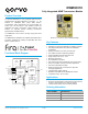


DWM3001C
Fully Integrated UWB Transceiver Module
DWM3001C Data Sheet Rev B, May 2022
Subject to change without notice | All rights reserved
4 of 27
www.qorvo.com
®
2. DWM3001C Calibration
Depending on the end-use applications and the system design, DWM3001C settings may need to be tuned. To help with this tuning a
number of built-in functions such as continuous wave TX and continuous frame transmission can be enabled. See the DW3000 User
Manual for further details.
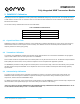
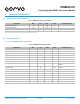
An overview of factory calibrated items is shown in the table below:
Table 1: DWM3001C Calibrated Items
DW3000 Calibration Item
Calibrated on DWM3001C
Crystal
✓
Transmit Power
✓
Antenna Delay
✓
2.1 Crystal Oscillator Trim
DWM3001C modules are calibrated at production at room temperature to minimise initial frequency error to reduce carrier frequency
offset between modules and thus improve receiver sensitivity. The calibration carried out at module production will trim the initial
frequency offset to less than 2 ppm, typically.
2.2 Transmitter Calibration
To maximize range, DWM3001C transmit power spectral density (PSD) should be set to the maximum allowable for the geographic
region in which it will be used. For most regions this is -41.3 dBm/MHz.
As the module contains an integrated antenna, the transmit power can only be measured over the air. The Effective Isotropic Radiated
Power (EIRP) must be measured, and the power level adjusted to ensure compliance with applicable regulations.
The DWM3001C provides the facility to adjust the transmit power in coarse and fine steps; 2 dB and 0.5 dB nominally. It also provides
the ability to adjust the spectral bandwidth. These adjustments can be used to maximize transmit power whilst meeting regulatory
spectral mask.
2.3 Antenna Delay Calibration
To measure range accurately, precise calculation of timestamps is required. To do this the antenna delay must be known. The
DWM3001C allows this delay to be calibrated and provides the facility to compensate for delays introduced by PCB, external
components, antenna and internal DWM3001C delays.
To calibrate the antenna delay, range is measured at a known distance using two DWM3001C systems. Antenna delay is adjusted until
the known distance and reported range agree. The antenna delay can be stored in OTP memory.*
*Note: For Engineering Samples DWM3001C.E1.0SR, DWM3001C.E1.0SQ, DWM3001C.E1.0SB and DWM3001CDKE1.0: do not
use the Channel 5 Antenna Delay in OTP – use default value 16390.