CM16a Amplifier Network Monitor HARDWARE MANUAL TD-000086-00 TD-000086-00 Rev.
¨ WARNING ¨ While QSC has endeavored to develop and produce the most dependable and robust ‘network’ audio product for your use, due to the myriad of network situations and equipment that may be encountered in its implementation, QSC cannot be held responsible for network conflicts and associated consequences that may result. For this reason, QSC strongly recommends that the network used for implementation of QSControl products be completed separate from all other networks, data or otherwise.
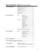
TABLE OF CONTENTS: CM16a Amplifier Network Monitor Section 1: INTRODUCTION Overview...................................................................................................5 Physical Characteristics & Layout........................................................6 List of Functions & Features...................................................................8 Block Diagram.........................................................................................9 Detailed Description of Functions..
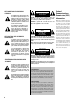
EXPLANATION OF GRAPHICAL SYMBOLS The lightning flash with arrowhead symbol, within an equilateral triangle, is intended to alert the user to the presence of uninsulated “dangerous voltage” within the product’s enclosure that may be of sufficient magnitude to constitute a risk of electric shock to humans.
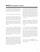
Section 1: Introduction- Overview The QSC CM16a Amplifier Network Monitor provides powerful The DataPort connections are made with ordinary VGA computer amplifier management and zone paging capability in a QSControl monitor-type cables (HD-15 male-to-male). These cables are networked audio system using Ethernet networking technology the same type that are used on personal computer systems to to communicate with the host computer/system controller. connect the monitor to the computer.
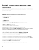
Section 1: Introduction- Physical Characteristics & Layout PHYSICAL CHARACTERISTICS Each CM16a is one rack space in height (1RU) and has an internal AC power supply. Its chassis depth is 37.7 cm (14.84 in.). The width of the chassis is 44.0 cm (17.32 in.). For the detailed mounting dimensions, please see specification section. The weight of the CM16a is approximately 5 kilograms (11 pounds).
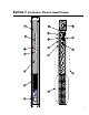
Section 1: Introduction- Physical Layout Diagram 7
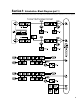
Section 1: Introduction- List of Functions & Features FUNCTIONAL LISTING, BLOCK DIAGRAM & DETAILED DESCRIPTIONS The CM16a performs control and monitoring of amplifiers remotely. Below is a listing of the functions that are available for the supported QSC amplifiers. The following two pages (Block Diagram part 1 & 2) graphically illustrate the main functions of the CM16a. Following the diagram is a section giving detailed explanations on each functional block that will aid in the use of the CM16a.
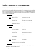
Section 1: Introduction- Block Diagram (part 1) The following diagrams illustrate the basic functional blocks of the CM16a. Keep in mind that the first diagram is “duplicated” for each of the eight ports.
Section 1: Introduction- Block Diagram (part 2) 10
Section 1: Introduction- Detailed Description of Functions AUDIO FUNCTIONS AUDIO MONITOR CHAIN FUNCTIONS Audio Inputs- These are the “Phoenix”-type 3 pin connec- Pre-Fader Monitor- Monitors the audio path at the point tors used for balanced line level audio-signal input. before the Level Control block (i.e. the input to the CM16a). Input Sensitivity- Sets the sensitivity of the Audio Inputs to Post-Fader Monitor- Monitors the audio path at the point either 1 Volt or 3 Volts (r.m.s.).
Section 1: Introduction- Detailed Description of Functions AMPLIFIER MONITORING FUNCTIONS Protect Status Detect- Reports if the amplifier has Amplifier Model Detect- Identifies what model of entered “protect” mode (such as thermal, over-current QSC amplifier is connected to the CM16a’s DataPort. or power-up muting protect status). Amplifier Gain Detect- Reports the setting of the Real Power Detect- Reports the “real” power the amplifier’s gain setting (in dB) for each channel.
Section 1: Introduction- Detailed Description of Functions RS-232 PORT FUNCTIONS CONTACT CLOSURE I/O FUNCTIONS RS-232 Port- The RS-232 (serial) port is used to RLY OUT- This is used for remotely controlling an electrical device in an on/off manner (such as a cooling fan, an audible alarm, a light, etc.). An internal SPDT (single-pole, double throw) relay is controlled by software command.
Section 1: Introduction- Network Description QSC CM16a Amplifier Network Monitors are designed to operate on standard 10BASE-T Ethernet. Each CM16a operates as a respective node on its network; each unit contains a programmable IP address in nonvolatile memory and will therefore present no conflict with any other node on the same network. Ethernet devices such as hubs, repeaters, switches and routers will usually afford the flexibility to configure the network as needed.
Section 1: Introduction- Sample Network Topologies The simplest network configuration is a single system controller computer and a CM16a connected by a single Ethernet crossover cable. A standard Ethernet cable would NOT work. The crossover-type cable must be used when connecting the CM16a directly to the system controller computer. This type of cable switches (or crosses over) the transmit and receive signals from one end to the other enabling connection without a hub or repeater.
Section 1: Introduction- Sample Network Topologies Some networks have multiple system controller computers. This configuration is essentially the same as the second example with the addition of the second computer attached to the hub. To create the more complex distributed star topologies needed for larger systems, use additional hubs. Some hubs have special uplink ports for connecting to other hubs via a standard Ethernet cable.
Section 2: Installation- Basics and Mounting UNPACKING There are no special unpacking precautions for the CM16a. However, it is recommended that you keep the original packing material for reuse in the rare event that service be required on the CM16a. If service is required and the original packing material is not available, ensure that the unit is adequately protected for shipment (strong box of appropriate size, sufficient packing material to prevent impact damage or load shifting).
Section 2: Installation- Mounting and AC Power MOUNTING THE CM16a (continued): The illustration below shows the basic mounting technique. The CM16a uses fan-drawn air for cooling. The air intake is on the left side of the chassis and the exhaust vents are on the front panel. Be certain not to obstruct these openings! Allow ample “open space” around them in order to maintain unobstructed air flow. Note that the CM16a’s recommended ambient operating temperature is 0°C. to 50°C. (32°F. to 122°F.).
Section 2: Installation- Connections CONNECTING AUDIO INPUTS REAR PANEL- AUDIO INPUTS The audio inputs are located on the rear panel. The CM16a uses “Phoenix”-type (Euro-style) terminal block connectors for the audio inputs. These connectors allow the installer to pre-wire the input terminations before the CM16a is installed in the rack. It also allows for re-routing of audio inputs by simply interchanging connector locations without the need for any tools.
Section 2: Installation- Connections CONNECTING PAGE INPUT The PAGE input is identical to the AUDIO INPUT connections. REAR PANEL- PAGE, RELAY & MONITOR CONNECTIONS Please refer to the previous page for connection guidelines. CONNECTING THE RLY/TRG IN The RLY/TRG IN connector is a two-pin version of the “Phoenix”-type connector. When using this input for a switchclosure (or opening) event, the two terminals should be connected to the switch contacts directly.
Section 2: Installation- Connections CONNECTION TO 10BASE-T (network connection) Connection to the Ethernet network is made using the RJ-45 type connector labeled 10BASE-T on the rear panel. The RJ-45 is the standard network connector for Ethernet networks. Insert the RJ-45 plug into the receptacle with the lock-tab oriented toward the bottom of the CM16a and push firmly until the connector locks into place (usually an audible “click” can be heard).
Section 2: Installation- Rear Panel Detail 22
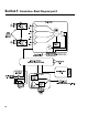
Section 2: Installation- Hookup Example 23
Section 3: Operation- General AMPLIFIER SETUP- The amplifiers connected to the CM16a should have their power switches in the ON position and their gain controls set as required by the user (seeInitial Testing note below). NOTE! For initial testing, it is advisable that the amplifiers be set for the lowest useful gain (volume) setting until it is verified that the system is operating as expected.
Section 3: Operation- LED Behavior & Bypass Switch Usage LED BEHAVIOR- When the power is switched ON, all of the LED’s light briefly and then the PORT LED’s sequence through two patterns. The LED’s then resume normal operation. The LED functions are described below. POWER LED- The power LED will illuminate whenever the power switch is in the POWER (ON) position. DIAGNOSTIC LED- This indicator first illuminates during the power-on self test of the CM16a, then should turn off.
Section 3: Operation- Bypass Switch Usage (continued) NOTE! Before depressing the BYPASS switch, the gain (volume) settings on all amplifiers connected to the CM16a should be reduced to a safe level. This is advisable because the CM16a’s “Level Control” will be reset to 0 dB. (or NO attenuation) with the BYPASS. It is possible that the amplifiers could be at maximum output level if the amplifier gain controls are not turned down.
Section 3: Operation- Serial Port I/O Interface The RS-232 connector on the rear panel is used as a serial port input/output (I/O). This I/O port is used for accessing controls for the IP address settings, system “health” data, firmware version information and other related data. Typically, this interface is not used by the majority of users. But should any system problems arise, the data that may be accessed through this interface can help to track down the problem.
Section 3: Operation- Serial Port I/O Interface 3) After starting Hyper Terminal, a Connection Description window will pop-up. It will require that you name your connection.Enter a name for your new connection (example: CM16a) and click OK to continue. 4) Next, Hyper Terminal needs to know how to “talk” to the CM16a. This selection depends on which port on your PC the null-modem cable is connected.
Section 3: Operation- Serial Port I/O Interface 6) The Hyper Terminal main window will appear next, but blank. Type the letter “h” (for help) and then the “Enter” key. This will prompt the CM16a to post its menu text. The “h” key is the Help prompt for the CM16a. 7) The next screen will look similar to the Hyper Terminal window above. After typing “h” and “Enter”, a text menu will appear. The menu should appear very similar to the example above.
Section 3: Operation- Telnet Access The features outlined for the RS-232 port can also be accessed via the Ethernet network connection. This feature can save a trip out to the remote CM16a with a laptop computer as long as the network and software are fully operable. The Telnet “session” is a standard Windows program. Consult Windows documentation for information reagrding the specifics of Telnet. It is a very straight-forward program to start and use.
Section 3: Operation- Fuse Replacement FUSE REPLACEMENT If the CM16a does not power-up when the POWER switch is in the “on” position (POWER indicator LED does not illuminate) check the source of AC power and the connection of the power cord at the outlet and IEC receptacle ends. If the AC source is “on” and the power cord is connected and in good condition, then the condition of the fuses should be checked. The fuse holder is an integral part of the IEC connector. It contains two fuses.
Section 4: Specifications- Dimensions Below are shown the dimensions s of interest for the CM16a. These dimensions are helpful for locating the rear-supports for the CM16a when used in portable or touring installations.
Section 4: Specifications Input Signal Processing Frequency response 20 Hz–20 kHz ±0.5 dB 10 Hz–80 kHz ±3 dB Distortion <0.01% THD+N @ +4 dBu out (page input <0.03%) Dynamic range >110 dB unweighted 20 Hz–20 kHz (page input >100 dB) Polarity In-phase or inverted Level control range -95.5 to 0 dB in 0.
Section 4: Specifications Power amplifier management Power amplifier interface Compatibility QSC Data Port equipped amplifiers Connector and cable HD-15 VGA cable, 2 meters length qualified (for longer runs, contact QSC’s Technical Services Department) Amplifiers Protect indicator Temperature meter Senses amplifier protect status Reports amplifier operating temperature Software adjustable threshold Over-Temp.
Section 4: Specifications Network Interface Physical network Raw data rate Frame format Connector Ethernet type Cable type Max cable length Grounding Ethernet, IEEE 802.3 compliant 10 megabits per second D.I.X.
SECTION 5: ARCHITECT’S AND ENGINEER’S SPECIFICATIONS The Amplifier Network Monitor shall provide input, output, and status control for DataPort equipped QSC power ampli- channel monitor signals. A monitor gain control fiers in an Ethernet-TCP/IP based network audio system. shall be provided for each monitor tap point to Sixteen independent channels shall be provided, grouped in adjust the individual levels of the channel monitor pairs.
Section 6: Appendix- Ethernet Cable Pinouts ETHERNET CABLING This diagram shows the pinout for standard unshielded twisted-pair (UTP) network cable. Both ends of the cable are wired identically. RJ-45 pinout for standard Ethernet patch cable (both ends identical) A crossover cable has the RX and TX wire pairs switched around at one end.
Section 6: Appendix- DataPort Pin-out & Connector P-N’s DATA PORT PINOUT: The diagram to the right shows the pin assignments used for the HD-15 connectors on the CM16a and amplifier. NOTE! This information is shown for reference only and is subject to change without notice as the DataPort feature is specific to QSC products and not intended for interface to other manufacturer’s equipment.
Section 7: How to Contact QSC Audio Products ADDRESS: QSC Audio Products, Inc. 1675 MacArthur Boulevard Costa Mesa, CA 92626-1468 USA TELEPHONE NUMBERS: Main Number (714) 754-6175 Sales Direct Line (714) 957-7100 Sales & Marketing (800) 854-4079 toll free in U.S.A. only Technical Services (714) 957-7150 (800) 772-2834 toll free in U.S.A. only FACSIMILE (FAX) NUMBERS: Sales & Marketing FAX (714) 754-6174 Technical Services FAX (714) 754-6173 WORLD WIDE WEB: http://www.qscaudio.
1675 MacArthur Boulevard Costa Mesa, California 92626 USA PH: (714) 754-6175 FAX: (714) 754-6174 “QSC” and the QSC logo are registered with the U.S.