DSP-3 Digital Signal Processor Amplifier Accessory Hardware Manual *TD-000087-00* TD-000087-00 Rev.
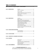
TABLE OF CONTENTS Warnings, Explanation of Graphical Symbols, and FCC Statement..............................................................4 Section 1: INTRODUCTION Overview......................................................................................................5 General Use Guidelines..................................................................6 QuickStart Guide............................................................................
WARNING! WHILE QSC HAS ENDEAVORED TO DEVELOP AND PRODUCE THE MOST DEPENDABLE AND ROBUST DIGITAL SIGNAL PROCESSOR (DSP) AUDIO PRODUCT FOR YOUR USE, DUE TO THE UNLIMITED AND POTENTIALLY DESTRUCTIVE (TO THE SOUND SYSTEM) CONFIGURATIONS THAT MAY BE APPLIED TO THE DSP BY THE USER, QSC CANNOT BE HELD RESPONSIBLE FOR DAMAGES RESULTING FROM ANY DEVIATION OR FAILURE BY THE USER TO STRICTLY FOLLOW THE RECOMMENDATIONS SET FORTH IN THE OWNER’S MANUAL FOR THE INTEGRATION OF THE DSP-3 AND SIGNAL MANAGER SOFTWARE WITH YOU
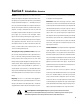
Section 1: Introduction- Overview The DSP-3 is a digital signal processor (or DSP ) accessory for 3 is mounted remotely on a rack-mount accessory that provides audio power amplifiers designed to reduce the need for exter- a solid physical mounting platform. nal signal processing while increasing overall system reliability through distributed intelligence.
Section 1: Introduction- DSP-3 General Use Guidelines IMPORTANT! Pleas read before operating the DSP-3 with your audio system. The DSP-3 is a professional level DSP product that allows the user to produce virtually unlimited signal processor variations and configurations.
Section 1: Introduction- Quick Start This quick start section is for those users who want to get up and running with the DSP-3 and Signal Manager software as quickly as possible. It is in no way a substitute for reviewing the contents of the entire hardware manual. It is intended for people familiar with the equipment discussed and should be followed up with a review of the manual and the software help file.
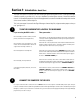
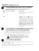
Section 1: Introduction- Quick Start 3 4 CONNECT THE AUDIO INPUTS If your using....... Then you need to...... the CHANNEL 1 INPUT & CHANNEL 2 INPUT connectors connect your input signal source to terminal block connectors (refer to page 18) and plug the connectors into the CHANNEL 1 INPUT and CHANNEL 2 INPUT receptacles. the DataPort input (QSC CM16a or related products) connect the DataPort output from the CM16a (or other related DataPort product) to the DataPort input of the DSP3.
Section 1: Introduction- Quick Start 5 INSTALL THE SOFTWARE 1. Place the QSC Signal Manager CD in your computer’s CD drive (typically the D:\ drive). The installation program should run automatically after several seconds; if it does not, then proceed with step 2: 2. Run D:\Setup.exe (replace D: with the drive letter designator appropriate for your system) and follow the instructions displayed. 3.
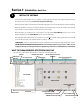
Section 1: Introduction- Quick Start 6 ESTABLISH COMMUNICATION BETWEEN THE DSP-3 & THE COMPUTER At this point, you should have everything “up and running”. In the Signal Manager application, check the COMMUNICATION STATUS PANE (lower right corner of the Signal Manager window, see above). If the COMMUNICATION STATUS PANE indicates..... Then you need to...... ONLINE Do nothing! Your communication settings match the COM port you connected the DSP-3 to.
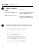
Section 1: Introduction- Quick Start n Now select the OUT1 icon from the same palette (left click on the OUT1 icon). Move your pointer into the upper right area of the workspace, in line with the IN1 object you just placed, and left click again. The OUT1 object should appear. n Select the GAIN icon in the MISC PROCESSORS palette (it looks like a little wedge and is the left-most icon in this palette).
Section 1: Introduction- Basic Connector & Indicator Descriptions FRONT PANEL CH 1 INPUT, CH 2 INPUT- These terminal-block CH 1 OUTPUT, CH2 OUTPUT-- These terminal- jacks (receptacles) are where you connect the block jacks provides post-DSP (processed) signal line-level audio inputs to the DSP-3. from the DSP-3 for downstream devices (ampli- They are electronically balanced with an input impedance of 8.3k Ohm. If used in an unbalanced configuration, the input impedance is 3.7k Ohms.
Section 1: Introduction- Basic Connector & Indicator Descriptions REAR PANEL DATAPORT (unlabeled)- This is the “output” DataPort. If the DSP-3 is directly mounted on a 2-RU QSC DataPort equipped amplifier, this connector plugs into the amplifier’s DataPort connector. If used with 3-RU QSC DataPort equipped amplifiers, the DSP-3 will need to be remotely mounted and a male-female DataPort cable used to interconnect the amp & DSP-3.
Section 1: Introduction- List of Functions & Features DSP-3 Hardware Features (full set available to QSC DataPort equipped amplifiers): High- and Low-Pass Crossover Selectable responses: Butterworth (6,12,18 or 24 dB per octave slope) Bessel (6,12,18 or 24 dB per octave slope) Linkwitz-Riley (12 or 24 dB per octave slope) Graphical response curve provided in software Adjustable frequency & slope Ability to bypass all EQ with a single mouse click Ability to add or delete EQ Assignable anywhere in signal c
Section 1: Introduction- List of Functions & Features Parametric EQ Adjustable frequency Adjustable gain Adjustable Q factor Ability to bypass all EQ with a single mouse click Ability to add or delete EQ Graphical response curve provided in software Assignable anywhere in the signal chain Signal Compressor Adjustable attack and release times Adjustable Gain Adjustable threshold Adjustable compression ratio Graphical response curve provided in software Assignable anywhere in the signal chain Signal Level
Section 1: Introduction- Block Diagram 16
Section 1: Introduction- Technical Overview This portion of the introduction provides some of the technical details of the DSP-3. Audio Input Path There are two audio channels each with two input connectors, a to non-QSC amplifiers (or any amplifier that does not have a balanced 3-pin ‘euro’ terminal block jack and an electronically DataPort). External power is provided by the accessory power balanced DataPort input.
Section 2: Installation- Unpacking and Mounting UNPACKING There are no special unpacking precautions for the DSP-3. However, it is recommended that you keep the original packing material for reuse in the rare event that service be required for your DSP-3. If service is required and the original packing material is not available, insure that the DSP-3 is adequately protected for shipment (strong box of appropriate size , sufficient packing material).
Section 2: Installation- Remote mounting (4-ch., Powerlight & non QSC amp’s) REMOTE MOUNTING THE DSP-3 : 4-Channel CX and DCA , Powerlight series, and all non-QSC amplifiers Use of the DSP-3 with the 4-channel CX and DCA and all Powerlight amplifiers requires the remote mounting of the DSP-3. Use with nonQSC amplifiers also requires remote mounting. Keep in mind that all applications that use amplifiers that do not have a DataPort ( i.e.
Section 2: Installation- Connections CONNECTING AUDIO INPUTS AND OUTPUTS: The audio inputs and outputs of the DSP-3 use 3-pin “Phoenix”-type (Euro-style) terminal block connectors. These connectors allow prewiring of inputs without any soldering and allow for rerouting of audio inputs by simply interchanging connector locations without the need for any tools. See Appendix for connector manufacturer’s part number reference.
Section 2: Installation- Connections DATAPORT Connection- This section applies to those users interfacing with the QSC DataPort products. If using the DataPort for your audio inputs, DO NOT use the terminal block inputs. If the DataPort is used only for control & monitoring of the amplifier (no audio input through the DataPort), then audio input may be via the terminal-block connectors. The front-panel DataPort connection is used for connecting to QSC DataPort products.
Section 2: Installation- Connections DAISY-CHAINING THE DSP-3 OUTPUTS TO ADDITIONAL AMPLIFIERS The DSP-3 provides audio output jacks for each channel. These outputs may be used for daisy-chaining the post-DSP signal to other amplifiers or for monitoring purposes. The signal on the output jacks is post-DSP. All signal processing functions done by the DSP-3 effect the signal provided to the output connectors as well. The terminal block outputs are active even when the DataPort connections are used.
Section 2: Installation- Application Examples The following examples show basic hook up information that assumes a two-channel, full range audio signal driving the load. Refer to your amplifier’s hardware manual for other output configurations. All audio signals are line level. DSP-3 Directly Mounted to QSC Amplifier. Audio Inputs via Terminal Block Inputs DSP-3 Directly Mounted to QSC Amplifier. Networked OR Local Control. Audio Inputs via DataPort.
Section 2: Installation- Application Examples DSP-3 Remotely Mounted used with QSC DataPort Amplifier. Audio Input via Terminal Block Inputs DSP-3 Directly Mounted to QSC Amplifiers, Networked Control via QSCcontrol Products NOTE: External accessory power supply may be required on older models, see Appendix for application information.
Section 2: Installation- Application Examples DSP-3 Remotely Mounted connected to any Non-DataPort Amplifier.
Section 3: Signal Manager Software- Software Installation System Requirements- To use QSC Signal Manager, you need the following hardware and software: • IBM compatible computer, 200 mHz or greater Pentium Processor • Windows 98/2000/ME or Windows NT 4.0 with service pack 6a or later • SVGA display at 800 x 600 minimum resolution, 1024 x 768 recommended • CD-ROM drive • 32 MB or more of RAM • 10 MB of free hard disk space • An available RS-232 serial communications port (COM port) capable of 38.
Section 3: Specifications Signal Processing 24 bit, 48 kHz. Common-mode rejection >50 dB, 20 Hz–20 kHz Frequency response at 3dB below full scale input voltage 20 Hz–10 kHz ±0.3 dB (term. block inputs) 20 Hz–20 kHz ±0.7 dB (term. block inputs) 20 Hz–20 kHz±0.2 dB (DataPort inputs) Crosstalk >75 dB separation, 20 Hz–20 kHz Distortion <0.01% THD+N @ +4 dBu out Delay (throughput) 687.5 microseconds Dynamic range >93 dB unweighted 20 Hz–20 kHz, 1.
Section 3: Specifications General Physical Height Width Depth 3.50 inches 3.75 inches 1.38 inches Weight 0.59 lbs (0.27 kg) Mounting Direct mount to amplifier or remote mount Operating temperature 0 to 50° Celsius Accessory External Power Supply AC Input Voltage 80–240 VAC AC Input Current 0.3 Amps rms Frequency 50 to 60 Hz Output Voltage 15 VDC Output Current 300 milliamperes Output Termination Detachable power cord with 2.
Section 4: Architect’s and Engineer’s Specifications The Digital Signal Processor (DSP) shall provide two independent Contact Closure I/O—The DSP shall provide a trigger input channels of DSP for signal delivery to QSC DataPort equipped usable for contact-closure (or other) purpose which shall power amplifiers. The processing shall be distributed with the DSP be CMOS & TTL signal compatible. module mounted directly to the rear of the power amplifiers.
Section 5: Appendix- DataPort Pinout DATA PORT PINOUT The diagram below shows the pin assignments used for the HD-15 connectors on the DSP-3 and amplifier. Pin Signal Description 1 Ch. 1 Minus (-) Input Signal 2 AC Standby Control tice as the DataPort feature is specific to 3 V- MON Ch. 1 and Subcode 1 QSC products and not intended for inter- 4 I- MON Ch. 1 and Subcode 2 5 Clip/Protect Ch. 1 6 Hard Ground 7 Ch. 1 Plus (+) Input Signal 8 Ch.
Section 5: Appendix- RS-232 Port Pinout & Connector P-N’s RS-232 PINOUT: The diagram below shows the pin assignments for the RS-232 connector on the DSP-3. Note that Pin #9 is used for Contact Closure function (normally not used in RS-232). Pin 1 2 3 4 5 6 7 8 9 Signal Description DCD TD RD DTR Signal GND DSR RTS CTS contact closure TERMINAL BLOCK CONNECTOR PART NUMBER REFERENCE- The following manufacturers and part numbers are provided as a reference to users.
Section 5: Appendix- Application Information APPLICATION INFORMATION As design improvements are continuous, the following information is subject to change. Contact QSC for current information. QSC’s DSP-3 Module has been designed to attach directly to the DataPort connector of QSC’s CX, DCA, Powerlight, and Powerlight 2 series amplifiers. When attached to CX, DCA, and Powerlight 2 amps manufactured 08/99 and later, the module receives its power through the DataPort from the amplifier.
Section 5: Appendix- Preset Operation Notes SPECIAL INFORMATION CONCERNING SAVED DSP-3 CONFIGURATIONS The computer which is used to create the DSP-3 signal flow configurations, and subsequently save them to disk, should be the same computer used to modify and adjust the DSP-3 settings in the future. Naturally, this might not always be the case.
Section 6: Maintenance, Warranty & QSC Contact Information Cleaning Disclaimer The faceplate and chassis can be cleaned with a soft cloth and QSC Audio Products, Inc. is not liable for any damage to speakers, nonabrasive, mild cleaning solution. Products like Simple Green amplifiers, or any other equipment that is caused by negligence or and Windex work well.
1675 MacArthur Boulevard Costa Mesa, California 92626 USA PH: (714) 754-6175 FAX: (714) 754-6174 © Copyright 2001, QSC Audio Products, Inc. QSC® is a registered trademark of QSC Audio Products, Inc., Costa Mesa, CA “QSC” and the QSC logo are registered with the U.S.