DSP-4 Digital Signal Processor Amplifer Accessory Hardware Manual *TD-000103-00* TD-000103-00 rev.
IMPORTANT SAFETY PRECAUTIONS & EXPLANATION OF SYMBOLS The lightning flash with arrowhead symbol within an equilateral triangle is intended to alert the user to the presence of uninsulated “dangerous” voltage within the product’s enclosure that may be of sufficient magnitude to constitute a risk of electric shock to humans. The exclamation point within an equilateral triangle is intended to alert the user to the presence of important operating and maintenance (servicing) instructions in this manual.
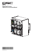
Introduction The DSP-4 is a digital signal processor (DSP ) accessory for audio power amplifiers. It is designed to reduce the need for external signal processing while increasing overall system reliability through distributed intelligence.
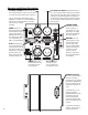
Connector and Indicator Descriptions CH 1 INPUT, CH 2 INPUT: balanced female XLR’s. If not using the DataPort for inputs, these are where you connect the line-level audio inputs to the DSP-4. They are electronically balanced with an input impedance of 8.3k Ohms. If used in an unbalanced configuration, the input impedance is 3.7k Ohms. Input sensitivity is software selectable. CH 1 OUTPUT, CH 2 OUTPUT: pseudo-balanced male XLR’s.
Introduction - Functions and Features The full set of features is available on QSC DataPort equipped amplifiers connected to the DSP module via the DataPort connector (direct-connect or remote-mount with DPX-2 cable). “V2” DataPorts and non-QSC amplifiers do not support Output Power Limiting. “V2” DataPort amplifiers and non-QSC amplifiers do not support Output Power Limiting.
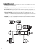
Introduction- Block Diagram Input Stage- Inputs are electronically balanced and RF filtered. The input sensitivity is software-selectable and any large signals are prevented from destroying the A-to-D by a diode. Output Stage- The output is buffered and then filtered to remove high-frequency sampling artifacts. Output sensitivity is softwareselectable and available from both sets of outputs simultaneously.
InstallationUnpacking It is recommended that you keep the original packing material for reuse in the rare event that service be required for your DSP-4. If service is required, and the original packing material is not available, insure that the DSP-4 is adequately protected for shipment (strong box of appropriate size , sufficient packing material). What is included in the carton: Item Description Quantity 1DSP-4 Digital Signal Processor 1 2#4-40 machine screw, 1.88” long 2 3#8-32 machine screw, 0.
Software Installation (continued) 5. Using the main menu bar at the top of the window, choose the “Help” item and read the software help section. The Help system includes the most up-to-date information for “paperless” reference. Also, visit QSC on the internet at http://www.qscaudio.com for DSP-4 updates. 6. IMPORTANT! The DSP-4 is shipped with all of its presets configured to pass full-range audio signals through both channels.
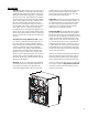
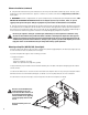
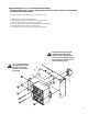
Remote mounting (4-ch., 8-ch., Powerlight & non QSC amp’s) The DSP-4 module requires “remote” mounting when used with the 4- and 8-channel CX, 4-channel DCA, Powerlight, and non-QSC amplifiers. If you have an amplifier that requires “remote” mounting, you need to: 1- Obtain the Accessory Remote Mounting Bracket. 2- Attach the right angle bracket to the module (see illustration, below). 3- Mount the module/bracket assembly on the main bracket.
DataPort Connections When using the DSP-4 module with QSC’s amplifier network monitors, the audio input to the module can be delivered through the DataPort along with amplifier control and monitoring signals. This is the normal application of the DataPort. Connection from the module to the amplifier network monitor is made using a DPC-X male-male QSC DataPort cable. Alternatively, the DataPort connection can be used ONLY for control and monitoring, while the audio is input via the XLR inputs.
Outputs- The DSP-4’s post-processor audio is output to the rear-panel DataPort AND the XLR output connectors. The outputs are electronically balanced with an impedance of 600 ohms. Output level is software-selectable from 4 or 6 Vrms. The XLR out’s can be used for daisy-chaining the processed audio to additional amplifiers, even when connected to a DataPort-equipped amplifier via the rear-panel DataPort.
DPX-1 Accessory Power Supply Connection to accessory external power supply (DPX-1) When the module is used with QSC amplifiers that do not provide +15 VDC through their DataPort connection OR is used with non-DataPort amplifiers, power must be supplied to the DSP-4 from an external power supply. All non-QSC amplifier applications require use of the DPX-1 accessory external supply. Contact QSC’s Technical Services Department or your QSC representative for more information.
Daisy Chaining Daisy chaining the DSP-4 outputs to additional amplifiers: The DSP-4 has two XLR audio outputs, one for each channel. These outputs may be used for daisy-chaining the post-DSP signal to other amplifiers or for monitoring purposes. The XLR outputs may be used for daisy-chaining even when the DataPorts are used for input/output. Do not use Output Power Limiting when daisy chaining. To daisy-chain the DSP output, connect the output jacks of the DSP-4 to the input jacks of the next amplifier.
USE- General Guidelines for Freely Configurable DSP The DSP-4 is configured (programmed) by using the included Signal Manager software. The software must be installed on your PC and the PC must be connected to the DSP-4 using a 9-pin serial cable and an available COM port. Once programmed, the module can operate without any connection to the computer. Any time changes are needed to the DSP’s configuration, the RS-232 connection must be active (cable connected).
Special Information About Saving DSP-4 Configurations (continued) Answering YES will open the Browse window. Once a configuration is selected, it is displayed on the screen, but not applied to the DSP-4. Answering NO will merely display a blank workspace to the screen with no configuration loaded. At this point, what is displayed is NOT what is currently running in the DSP-4 memory.
SPECIFICATIONSAudio converters Resolution and Sampling Rate Frequency response at 3 dB below full scale input voltage 24-bit resolution, 48 kHz sampling rate 20 Hz–10 kHz ±0.3 dB (XLR outputs) 20 Hz–20 kHz ±0.7 dB (XLR outputs) 20 Hz–20 kHz±0.2 dB (DataPort outputs) Distortion <0.01% typical THD+N @ +4 dBu out, 20 Hz–20 kHz Delay (throughput) 1.5 millisecond Dynamic range >104dB min., unweighted, 1.5V input sensitivity >106dB min., unweighted, all other input sensitivities >107dB min., A-weighted, 1.
SPECIFICATIONSPower Amplifier Connectivity Compatibility all professional audio power amplifiers Full Feature Set all QSC DataPort-connected amplifiers (“V2” DataPort reduced set) Features Supported by QSC DataPort Amps channel CLIP sensing, PROTECT status, active Power Limiting DataPort Connector & Cable (if using) proprietary pinout HD-15 connector, 1 female “input” DataPort and 1 male “output” DataPort.
Architect’s and Engineer’s Specifications The Digital Signal Processor (DSP) shall provide two independent channels of DSP for signal delivery to QSC DataPort equipped power amplifiers. The processing shall be distributed with the DSP module mounted directly to the rear of the power amplifiers. Output Power Limiter—For each audio channel, the DSP shall provide a power limiter that is assignable anywhere in the signal chain and can be switched on or off.
APPENDIXDataPort Pinout NOTE! This information is shown for reference only and is subject to change without notice as the DataPort feature is specific to QSC products and not intended for interface to other manufacturer’s equipment. NOTE! Powerlight 6.0 and Powerlight 9.0 amplifiers require that pin #9 be removed from the remote mounting interconnect cable (DPX-2). Amplifier damage may result from use of cable that has pin #9 connections present.
APPENDIXBalanced connection is recommended for all inputs. The XLR inputs on the DSP-4 are electronically balanced. Balanced input cables are recommended to minimize noise pick up and prevent ground loops. If constructing your own cables, refer to the pinout, above, for proper connector wiring. XLR input pinout (balanced) - + pin 2 - pin 3 + pin 1 Unbalanced inputs can be used if required.
APPLICATION INFORMATION As design improvements are continuous, the following information is subject to change. Contact QSC for current information. QSC’s DSP-4 Module has been designed to attach directly to the DataPort connector of QSC’s CX, DCA, and Powerlight 2 series amplifiers. When attached to CX, DCA, and Powerlight 2 amps manufactured 08/99 and later, the module receives its power through the DataPort from the amplifier.
NOTES- 22
NOTES- 23
How to Contact QSC Audio Products Mailing address: QSC Audio Products, Inc. 1675 MacArthur Boulevard Costa Mesa, CA 92626-1468 USA Telephone Numbers: Main Number (714) 754-6175 Sales & Marketing (714) 957-7100 or toll free (USA only) (800) 854-4079 Customer Service (714) 957-7150 or toll free (USA only) (800) 772-2834 Facsimile Numbers: Sales & Marketing FAX (714) 754-6174 Customer Service FAX (714) 754-6173 World Wide Web: www.qscaudio.com E-mail: info@qscaudio.com service@qscaudio.