ISIS WideLine Loudspeaker User Manual Manual del usuario para los altavoces ISIS WideLine Manuel de l'utilisateur des haut-parleurs ISIS WideLine ISIS WideLine-Lautsprecher – Benutzerhandbuch ISIS WideLine 扬声器用户手册 WL2102 Cored Composite Enclosure WL2102-w Birch Plywood Enclosure Stacking Frame Fly Grid *TD-000227-00* TD-000227-00 rev.
IMPORTANT SAFETY PRECAUTIONS Install in accordance with QSC Audio Product's instructions and under the supervision of a licensed Professional Engineer. WARNING! Before placing, installing, rigging, or suspending any speaker product, inspect all hardware, suspension, cabinets, transducers, brackets and associated equipment for damage. Any missing, corroded, deformed, or non-load rated component could significantly reduce the strength of the installation, placement or array.
Introduction The WideLine loudspeaker system has been designed to provide a compact system that has unique power handling, frequency response. Its primary uses include ballrooms, theatres, night clubs, houses of worship, and small to medium size events for the corporate and industrial markets. WL2102 enclosures are constructed of lightweight cored-composite and weigh 70 lb (31.8 kg). WL2102-w enclosures are constructed of birch plywood and weigh 83 lb (37.7 kg).
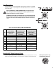
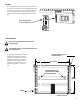
TRI AMP/BI AMP Switch TRI AMP: Shading network is NOT applied (shading must be provided by upstream signal processing). Connect the fullrange input signal to pins 1+ and 1-, connect the shaded (processed) signal to pins 2+ and 2-. To flip shaded transducer location, use the MF (UNSHADED) SELECT switch or alter signal processing. Default MF (UNSHADED) SELECT switch position for three way mode is position A; if put in position B, connections (per Table 1) to LF transducers A and B are interchanged.
Input Connections The input connectors are a pair of Neutrik NL8's wired in parallel. Connections for bi amp and tri amp vary, see Table 1. The pin designations for the NL8FC cable connector is shown for reference, bottom right. Note! In TRI AMP mode, the MF (UNSHADED) SELECT switch position determines the input connector wiring! Unexpected results may occur if switch positions and wiring are not strictly controlled. The WideLine loudspeaker is not equipped with a crossover network.
Rigging Rules for Suspension •Correct use of all suspension hardware and components is imperative in sound system rigging and deployment. •Always calculate suspended loads before lifting to ensure suspension components and hardware are used within their respective load limits. •Research local codes and regulations to fully understand the requirements for suspended loads in the venue in which the equipment is to be suspended. •Use only shackle holes for suspension of array.
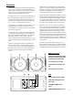
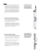
Rigging WideLine enclosures use a three-point suspension system. The system consists of front, left/right, captive articulated joints and a single rear link bar. Articulation is in 2° increments using the first location on the link bar. With the use of the second location, 1° degree increments can be obtained starting at 3°. The total available angular increments are: 0, 2, 3, 4, 5, 6, 7, 8, 9, and 10°. All pieces and locking pins remain with the enclosures.
Adjusting the Angle Between Enclosures (Splay) The illustration shows the rear pin block of two enclosures joined by the upper enclosure’s rear link arm. Use the first pin location (closest to the end) on the link arm for setting in normalized 2° increments. The left-side example shows two enclosures linked for 8° of splay. The ball-lock pin is inserted into the 8° position in the rear block while passing through the “normal” pin hole in the link.
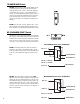
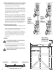
Fly Grid The mounting plate and link bar are located on the bottom side of the frame assembly. Use this link for attaching the rear of the first enclosure. The frame allows for up or down angle options for use with either stacking or suspending. The 4° “normal” locations on the link system will yield a net 0° vertical inclination. Use 4° link location for 0° vertical inclination Stacking Frame Do not stack more than four (4) enclosures on a Stacking Frame. Use only 5/16” diameter x 1.
Stacking the Stacking Frame The Stacking Frame comes with two aluminum I-bars used for aligning and securing the frame to QSC’s 215SB or 215PCM subwoofer. To use the I-bars, simply slide each one into the small frame’s L-track and secure with a stud fitting. Then, turn the frame over (I-bars on the bottom) and slide the exposed I-bars into the subwoofer’s L-track. Secure the I-bar with a stud fitting.
System Specifications (subject to change without notice) Configuration: Three way, bi amp or tri amp Frequency Response1: 55 - 18,000 Hz (+/- 3 dB) Frequency Range: 48 - 20,000 Hz (-10 dB) Sensitivity: LF: 98 dB (1W @ 1m) HF: 107.5 dB (1W @ 1m) Nominal coverage: Horizontal: 140 degrees Nominal Impedance: LF: bi amp mode 8 Ohm, tri amp mode 16 Ohm. Transducers: LF: Two 10 inch (254mm) long excursion, high power, 3 inch (76mm) voice coil, 16 Ohm, 400W each2 HF: 3.0 inch (76mm) diaphragm, 1.
Dimensions- WL2102 and WL2102-w 20.75” (527mm) NOTE! Composite enclosures have approximately 1° of draft on the enclosure sides; the birch plywood enclosures do not. Handle orientation may vary between composite and plywood enclosures. 10.75” (273mm) 7.7” (196mm) 20.4” (518mm) 27.5” (699mm) 25.0” (635mm) 10.1” (257mm) 26.
How to Contact QSC Audio Products Mailing address: QSC Audio Products, Inc. 1675 MacArthur Boulevard Costa Mesa, CA 92626-1468 USA Telephone Numbers: Main Number (714) 754-6175 Sales & Marketing (714) 957-7100 or toll free (USA only) (800) 854-4079 Customer Service (714) 957-7150 or toll free (USA only) (800) 772-2834 Facsimile Numbers: Sales & Marketing FAX (714) 754-6174 Customer Service FAX (714) 754-6173 World Wide Web: www.qscaudio.com E-mail: info@qscaudio.com service@qscaudio.