
Manual


3 (DRAFT 2014/07/22)
TD-000432-00-A
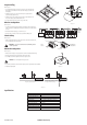
Prepare Ceiling
Refer to Figure 1.
1. Use the template provided to mark and cut a hole (1) in the ceiling where the
loudspeaker is to be installed. For frame-construction ceiling, skip to "Wire the
Loudspeakers".
2. Install two V-rails (2), one on each side of the hole, and supported by the
suspended-ceiling support rails (3).
3. Install the C-ring (3) over the hole, using the V-rails as support. Make sure the
clips on the C-ring are properly fitted over the V-rail.
4. Use sheet-metal screws (5) to secure the C-ring to the V-rails.
Wire the Loudspeakers
Refer to Figure 2.
1. Pass the wires down through the conduit/stress-relief clamp. Leave enough wire for
making connections. Carefully tighten the clamp over the wires, or over the conduit if
it is used.
2. Wire the female Euro-style plug (1) as shown in Figure 3.
3. Slide the cover (3) over the connector and secure with the Phillips screw.
Seismic Safety
Refer to Figure 4.
1. Attach an appropriate safety line to the safety tab on the back of the connector cover,
and to an appropriate part of the structure.
WARNING!:
Be sure to check and adhere to local building codes for
seismic requirements.
Mount the Loudspeaker
Refer to Figure 5.
1. Make sure all of the dog-ears are up against the side of the metal loudspeaker housing.
2. Slide the Loudspeaker Housing up through the hole into the ceiling.
3. Use a Phillips screwdriver to tighten each of the four dog-ear screws.
CAUTION!:
Do not overtighten the dog-ear screws!
4. Use a flat-tip screwdriver to set the transformer tap based on the requirements of the installation.
5. Install the loudspeaker grill.
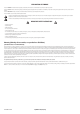
Specifications
Name Specification
Transducer 4” Polypropylene cone with rubber surround
Rated noise power [W rms]
(1)
16
Nominal Impedance 8 Ohm
Transformer Taps 1, 2, 4, 8, 16W, 8 Ohms bypass, 70 and 100V
Effective frequency range [Hz]
(2)
70 – 16k
Rated coverage [degrees]
(3)
140 conical
Sensitivity [dB]
(4)
89
Maximum continuous SPL [dB]
(5)
101
Maximum peak SPL [dB]
(5)
107
— Figure 1 —
1
2
3
4
5
— Figure 2 —
1
3
4
2
— Figure 3 —
Parallel Wiring Diagram
Amp
To more
speakers
From
Source
To Additional
Loudspeakers
1
— Figure 4 —
— Figure 5 —
Turn the screw clockwise to engage
the dog-ear with the ceiling.
Dog-ears against loudspeaker
1 2