AD-C Series AD-C820/AD-C821/ AD-C1200 User Manual AD-C820 – 203 mm (8") 2-way coax baffle assembly AD-C800BB – Pre-install enclosure for AD-C820 AD-C821 – 203 mm (8") 2-way coax blind-mount AD-C800 RAIL KIT – Split Ring and Tile Rails for AD-C821 AD-C800RG – Round Grille for 8" loudspeaker AD-C800SG – Square Grille for 8" loudspeaker AD-C1200 – 304 mm (12") 2-way coax baffle assembly AD-C1200BB – Pre-install enclosure for AD-C1200 AD-C1200SG – Square Grille for 12" loudspeaker TD-000296-00 REV.
IMPORTANT SAFETY PRECAUTIONS AND EXPLANATION OF SYMBOLS WARNING! 1. Read these instructions. 2. Keep these instructions. 3. Heed all warnings. 4. Follow all instructions. 5. Clean only with a dry cloth. 6. Install in accordance with QSC Audio Product’s instructions and local building codes. The installation should be done by a licensed installation professional. 7. Do not install near any heat sources such as radiators, heat registers, stoves, or other apparatus (including amplifiers) that produce heat. 8.
Introduction Congratulations and thank you for your ceiling loudspeaker purchase. The AD-C820, AD-C821 and AD-C1200 models offer excellent acoustic performance in an easy-to-install and attractive package. Please review these instructions carefully and follow the recommendations. Installation should be done by a licensed installation professional and in accordance with these instructions and local building codes.
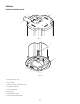
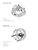
Features AD-C821 Loudspeaker System d c e b a – Figure 1 – f g h – Figure 2 – a. Pivoting connection cover b. Euro connectors c. Pivoting connection cover retaining screw d. Loudspeaker wiring hole e. Seismic mounting tab f. Mounting tabs g. Grille attachment magnets h.
AD-C820 Loudspeaker Baffle a b c a. Mounting tabs – Figure 3 – b. Grille attachment magnets c. Tap Switch (transformer included in AD-C800BB) AD-C800BB Back Box Sold separately for use with AD-C820 Loudspeaker Baffle a a b a c e a d a a. Dual Knockouts (½" and ¾") (Qty: 5) – Figure 4 – b. Ceramic terminal block c. Transformer d. Mounting straps (Qty: 4) e.
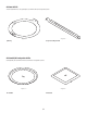
AD-C800 Rail Kit The AD-C800 RAIL KIT is sold separately for use with the AD-C821 loudspeaker system.
AD-C1200 Loudspeaker Baffle a c b d – Figure 9 – a. Dual Euro connectors b. 150 W Transformer for 70/100 V distributed loudspeaker systems c. Crossover network d. Installation hook AD-C1200BB Back Box Sold separately for use with AD-C1200 Loudspeaker Baffle b a a a a c a – Figure 10 – a. Dual knockouts (½" and ¾") (Qty: 5) b. Mounting tabs (Qty: 4) c.
AD-C1200SG Loudspeaker Grille – Figure 11 – AD-C821 Installation Options The AD-C821 Loudspeaker System is a blind-mount design made to mount into finished ceilings. The AD-C821 loudspeaker system can be mounted in suspended ceilings, as well as non-suspended ceiling types. We recommend that you consult an installation professional for safety assurance, quality installation, and optimum acoustic performance.
AD-C821 Installation Tools and Parts Required for Installation 1. #2 Phillips head screwdriver 2. Torque driver 3. Wire stripping tool 4. Soldering equipment 5. Tool for cutting loudspeaker mounting hole in ceiling. Must be able to cut a circular hole through the ceiling without damaging the structural integrity of the ceiling. 6. Small flat-tip screwdriver for securing wires in Euro-style connector. 7.
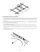
15.16" 395 mm – Figure 12 – Install Split Ring and Suspended-ceiling Tile Rails 1. Skip this step if installing in a non-suspended ceiling. Pass the two Suspended-ceiling Tile Rails (Figure 6) through the hole and place on both sides of the mounting hole 15.16" (395 mm) apart, as shown in (Figure 12) and install onto the ceiling T-rails.
Support and Wire the Loudspeaker System Important: Loudspeakers can potentially generate substantial vibration. In addition to ensuring all hardware is properly installed and secure, you must use the Seismic Support Bracket on the loudspeaker to secure the loudspeaker to an appropriate structural support. This minimizes the chance of the loudspeaker falling from the ceiling in the event the primary mount fails.
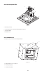
AD-C800BB and AD-C820 Installation The AD-C800BB is designed to be pre-installed into the ceiling and wired. The AD-C820 Loudspeaker Baffle assembly is plugged into and secured to the back box at a later time. AD-C800BB Back Box Installation The AD-C800BB installation should be done by a licensed installation professional and wiring installed by a licensed electrician in accordance with local building codes. 1.
d c b – Figure 17 – a a. Facility’s loudspeaker signal wiring b. Ceramic terminal block c. Wiring to loudspeaker baffle d. Wire holding screws AD-C820 Installation 1. Connect the 10-pin Mate-N-Lok™ connector from the AD-C800BB to J1 on the transformer tap switch PCB. 2. Connect the 3 Faston connectors to the crossover points J2, J3, and J4 on the larger PCB. Note: J2, J3, and J4 are labeled for the proper wire color.
Mount the AD-C820 or AD-C821 Loudspeaker System Note: The Mounting Clamps are part of the assembly and allow for mounting surfaces (ceiling) up to 2.75" in thickness. Do not install the grille until clamps have been tightened and any adjustments made. 1.
2. Make sure all tests and adjustments are complete before installing the grille. 3. Locate the loudspeaker grille. 4. The loudspeaker system and grille both have a Grille-retaining Safety Tether. Using the clip on the grille’s tether, attach the grille’s safety tether to the loudspeaker’s safety tether. Refer to (Figure 22) for details regarding the clip. a b a. Loudspeaker tether – Figure 21 – – Figure 22 – b. Grille tether a b b c a a.
AD-C1200 and AD-C1200BB Installation The AD-C1200BB back box is designed to be pre-installed into the ceiling and wired. The AD-C1200 Loudspeaker Baffle assembly is plugged into and secured to the back box at a later time. AD-C1200BB Installation The AD-C1200BB installation should be done by a licensed installation professional and wiring installed by a licensed electrician in accordance with local building codes. 1. There are 5 wiring ½" & ¾" knockout locations available on the AD-C1200BB (Figure 10) .
d c b a – Figure 24 – a. Facility's loudspeaker signal wiring b. Ceramic terminal block c. Wiring to loudspeaker d. Wire holding screws AD-C1200 Installation Note: AD-C1200 comes pre-wired, from the factory, for transformer tap applications. To bypass the transformer see “Remove Transformer from the AD-C1200 Circuitry” in this section. 1. Locate and remove the five-pin Euro-style connector plug included with the loudspeaker baffle assembly.
75 W 37.5 W COM 37.5 W 18.75 W PRIM LO Z- 150 W 75 W LO Z+ N/A 150 W J1 100V 70 V J2 – Figure 25 – 1. Tighten the M3 wire retaining screws. 2. Reconnect the five-pin Euro-style connector plug into its mate on the PCB. Make sure all connections are secure. Caution: The AD-C1200 Loudspeaker Baffle assembly weighs 25 lbs (11.3 kg.) Be sure to use proper safety precautions. 3. Lift the loudspeaker baffle assembly into back box enclosure.
a b a a a a a a. Baffle mounting holes — 6 places c – Figure 27 – b. Grille mounting holes — 4 places c. Extra mounting holes — 4 places 5. Locate the loudspeaker’s grille. 6. Using a #2 Phillips head screwdriver, install the grille with the M4 screws provided. Note: The use of LOCTITE® is recommended to prevent grille screws from loosening during use. Note: The extra mounting holes, shown as item c (Figure 27), are to be used with previously installed enclosures from other manufacturers.
Disconnect Transformer from the AD-C1200 Circuitry If you are connecting the loudspeaker to a 16 ohm system, you must disconnect the transformer. 1. Unplug the two-pin Euro-style plug (J1) on the PCB (Figure 25). 2. Loosen the two M3 wire securing screws using a #1 Phillips head screwdriver and remove the wires. 3. Secure and insulate all the wires you removed using a tie-wrap or similar device. This is to prevent rattling during loudspeaker operation. 4.
Dimensions AD-C800BB 10.9" 11.2" 275.7 283.7 mm mm 8.0" 202.3 mm 0.3" 0.8 mm 11.8" 299 mm Ceiling Cutout Dim = Ø 305 mm AD-C821 11.5" 292.1 mm 11.5" 292 mm Note: The 11.5" measurement is the actual dimension of the hardware. For cutting the mounting hole, refer to the Cut Mounting Hole in Ceiling section in this document.
Dimensions Continued AD-C1200BB 15.5" 394 mm 15.0" 381 mm 14.6" 371 mm 23.0" 584 mm 14.6" 371 mm 17.9" 555 mm 20.
Specifications AD-C820/AD-C800BB AD-C821 System Configuration Passive Passive Frequency Response (-6 dB) 61 Hz – 18 kHz 61 Hz – 18 kHz 42 Hz – 18 kHz Frequency Range (-10 dB) 52 Hz – 18 kHz 52 Hz – 18 kHz 37 Hz – 18 kHz System calculated maximum Output (RMS) 114 dB 114 dB 118 dB (Peak) 120 dB 120 dB 124 dB 1.4" 1.4" 1.
Mailing Address: QSC Audio Products, LLC 1675 MacArthur Boulevard Costa Mesa, CA 92626-1468 USA Telephone Numbers: Main Number: (714) 754-6175 Sales & Marketing: (714) 957-7100 or toll free (USA only) (800) 854-4079 Customer Service: (714) 957-7150 or toll free (USA only) (800) 772-2834 Facsimile Numbers: Sales & Marketing FAX: (714) 754-6174 Customer Service FAX: (714) 754-6173 World Wide Web: www.qscaudio.com E-mail: info@qscaudio.com service@qscaudio.com © 2010 QSC Audio Products, LLC.