
Owner's Manual


TD-001564-01
3
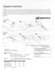
Wire the Subwoofer
We recommend using insulated twisted pair stranded copper wire of an
adequate gauge to minimize resistive losses. To facilitate connection,
the AD-P.SUB loudspeakers have a four-pole connector for the input and
two more for the high-pass outputs to as many as four 16Ω satellite
loudspeakers (Figure 5). Each subwoofer comes with three Euro-style four-
pole pluggable connectors with clamping screws for securing to the wire
conductors.
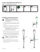
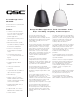
1. Remove the magnetic grille and set the transformer tap switch to the
desired power (in watts) or to 4Ω for low-impedance operation (Figure
6). Reattach the grille. This setting can always be readjusted in the
future as needed.
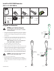
2. On the top of the enclosure, remove the two protective covers over
the input and output connectors. The smaller cover has one gland
(protective cable pass-through) and the larger one has two.
3. Route the wires coming from the amplifier through the gland in the
smaller cover. Route the wires for the satellte loudspeakers through one
or both glands on the larger cover.
4. Strip the wire ends about 6 mm or about 1/4 inch.
5. Connect the pairs of wires to the + and - terminals of the Euro-style
connectors as shown in Figure 7. Tighten the clamping screws to hold
the wires securely.
To daisy-chain forward to another loudspeaker, route a second wire
pair through the gland and attach them to the THRU terminals of the
input Euro-style connector. Be mindful of polarity when connecting
multiple loudspeakers; always connect + to + and – to –.
6. Plug the connectors into their respective locations and tighten their
retaining screws. Reinstall the protective covers and tighten the gland
nuts to secure the wires.
7. To strain-relieve the wires, secure them to a hanger cable using the
tie-wraps provided.
WARNING!: Install the system in accordance
with local building codes and regulations. Some
jurisdictions may require additional suspension
points.
Use a licensed contractor or professional
engineer. QSC is not responsible for damages
that result from negligent installation of any
bracket, hanger, or loudspeaker.
— Figure 4 —
100
50
4Ω
25
12.5
25
50
100
N/A
4Ω
70
Volts
100
Volt
s
— Figure 6 —
AD-P.SUB
ACOUSTIC DESIGN
PENDANT SUBWOOFER
INPUT: 70V, 100V, LOW-Z (4Ω)
MAXIMUM POWER RATING: 100 W RMS/200 W PROGRAM
HI-PASSFILTERED (200Hz-20kHz)
OUTPUTS TO 16Ω SATELLITE SPEAKERS
SAT 1 SAT 2SAT 3 SAT 4
— Figure 5 —
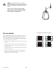
To SAT 1To SAT 2To SAT 3
(if needed)
To SAT 4
(if needed)
Amp
To other subwoofers
THRU
— Figure 7 —