
Owner's Manual


EN
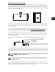
Wiring Signal to the Subwoofer
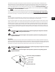
The input terminal is on the rear of the subwoofer and is covered by a hinged door. Open the door to expose the screw
terminals. There are four sets of screw terminals arranged in positive/negative pairs for parallel wiring. One pair is labeled
for input (receive signal) and the other pair is labeled for output (pass signal to next device). But be sure that the wiring is
consistent and paired properly.
The terminals are designed to accept wiring between 18 AWG (1.02 mm) and 12 AWG (2.053). Use a #2 Phillips-head screw
driver to loosen the terminal screw. Strip the insulation for the signal wire so that approximately 3/4 in (20 mm) of bare wire
is exposed. Place the bare wire under the screw down plate and retighten the screw as tightly as possible with a manual
screw driver.
The input and output pairs are parallel. The output terminals will pass exactly what is presented at the input terminals. If low
impedance full range audio signal is presented at the input (it is recommended that the subwoofer’s internal low pass filter
be used in this instance) then low impedance full range audio will be passed to the next device wired to the parallel output
of the AD-S28Tw. If high impedance 70V or 100V signal is presented at the input, then high impedance 70V or 100V signal
will be passed to the next device wired to the parallel output of the AD-S28Tw. If an external low pass filter is used and only
low passed signal is presented at the input, then only low passed audio will go to the next device wired to the parallel output
of the device.
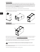
Using 70V or 100V Drive for Distributed Audio Systems
High impedance 70V or 100V drive allows for a typically larger number of loudspeakers to be wired to one amplifier output
and allows smaller wire gauge to be used over longer runs with less loss. When using high impedance drive, the internal
transformer on the AD-S28Tw MUST be engaged. To do this, rotate the tap selector switch so that it is aligned with one of
the four (three for 100V) transformer tap settings. The tap setting on the switch selects which tap of the transformer is used
to buffer the signal and is expressed in terms of the power draw on the amplifier. The larger the tap, the more output from
the subwoofer. Transformer tap settings should be considered when selecting an amplifier to drive the system. A good “rule
of thumb” is that the rated power of the amplifier per channel should be the minimum of all of the connected taps added
together with an additional 20% for headroom. An example:
8 Loudspeakers each tapped at 50W
50 + 50 + 50 +50 + 50 + 50 + 50 + 50 = 400 or 8 x 50 = 400
400 + 20% = 480 Use an amplifier with a minimum channel power rating of 480W
Multitap 70V / 100V transformers can saturate with low frequency energy. Saturation causes analog clipping distortion of
the signal. The transformer use in the AD-S28Tw is custom designed to saturate at frequencies below the functional low
frequency range of the AD-S28Tw. It is recommended that a -6 dB, 30 Hz high pass filter be engaged to prevent saturation of
the transformer.
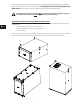
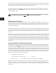
Any unused attachment point can be used as a safety/seismic secondary attachment. Attach an eyebolt to an available
attachment point according to the Eyebolt instructions above. Be sure to leave less than 12 in (300 mm) of slack in the
secondary attachment cable.
The safety/seismic secondary attachment must be secured to structure that is capable of supporting
the weight of the subwoofer and must be connected using load rated hardware.
Once the subwoofer is secured in position, the QSC logo can be rotated if desired. If the logo is difficult to rotate the first
time, a tool may be required. A small flat-head screw driver is recommended. Gently work the tool between the logo badge
and the grille to allow rotation. Exercise care to avoid scratching the grille surface.
8