BASIS 904zz 16 Output CobraNet Enabled Control and Monitoring Signal Processor Hardware Manual *TD-000152-00* TD-000152-00 rev.
IMPORTANT SAFETY PRECAUTIONS & EXPLANATION OF SYMBOLS The lightning flash with arrowhead symbol within an equilateral triangle is intended to alert the user to the presence of uninsulated “dangerous” voltage within the product’s enclosure that may be of sufficient magnitude to constitute a risk of electric shock to humans. The exclamation point within an equilateral triangle is intended to alert the user to the presence of important operating and maintenance (servicing) instructions in this manual.
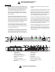
Don’t want to read the entire manual? Just want to dig right in? Go to page 18.... Introduction The BASIS 904zz provides the digital audio transport, signal processing, control and status monitoring facilities needed to bind a group of amplifiers and loudspeakers into an integrated functioning system. In conjunction with QSControl.
Introduction (continued) The BASIS 904zz also supports the new optional lowlatency CobraNet feature that provides transport at only 2.66 milliseconds delay. Both software and firmware can be easily updated over the network. In the future, QSC will be adding new capabilities to both BASIS and QSControl.net. Our latest code releases and access to up-to-date information on BASIS and QSControl.net are available at www.qscontrol.net. We invite you to visit us there.
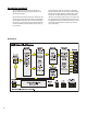
Introduction - Networking the BASIS 904zz The BASIS 904zz has two RJ-45 network connection ports on the rear panel. One port is labeled "QSControl" and supports standard 10BASE-T Ethernet. The other port is labeled "CobraNet" and supports 100BASE-TX, also known as "Fast Ethernet". In the following we describe the use of these ports and show example network connection schemes.
Third, the BASIS 904zz and QSControl.net system are targeted at network switch deployments. The consumer costs of Ethernet switches have continued to fall over the last several years and are now comparable with repeaters on a per port basis. In addition, the sophistication and scalability of network switches make them ideal for new installations. However, we do realize that designers may wish to add BASIS products to existing audio network installations that are built on repeater LAN topologies.
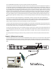
Example #2 - CobraNet X-over mode: This is the simplest connection you can make between two BASIS/RAVE units. You use a CAT-5 crossover cable connected between the CobraNet ports of each unit. No network switch is required. This connection allows audio to pass between the two units over CobraNet. The BASIS 904zz is an audio “destination” device, therefore, the other unit must be an audio “source” device puting CobraNet audio data onto the cable.
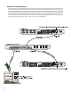
Example #3 - Single Wire Interface: Here all QSControl and CobraNet traffic shares the same single CAT-5 cable between the BASIS 904zz and an unmanaged Ethernet switch. The QSControl.net system manages traffic flow efficiently and reliably so that all audio and control data is delivered to its appropriate destination anywhere on the network. This configuration works well when CobraNet audio deliveries are point to point.
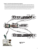
Example #4 - Two-Wire Interface (shared network hardware): This example illustrates the Two-Wire Interface with a managed Ethernet switch. The switch is configured with multiple virtual local area networks (VLANs). Ethernet deliveries can only reach destination ports belonging to the same VLAN from which it was sourced. The figure shows a separate VLAN for QSControl.net traffic and a separate VLAN for CobraNet audio traffic.
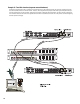
Example #5 - Two-Wire Interface (separate network hardware): Example #5 is conceptually similar to example #4. The difference here is that separate networks are created by providing each local area network (LAN) with its own network switch. Therefore, traffic segmentation is physical rather than logical. Example #5 also provides an additional level of fault tolerance, although at the expense of additional network hardware. The figure shows a separate network switch for QSControl.
Unpacking There are no special unpacking precautions. However, it is recommended you keep the original packing material for reuse in the rare event that service be required. If service is required and the original packing material is not available, ensure that the unit is adequately protected for shipment (strong box of appropriate size, sufficient packing material to prevent load-shifting or impact damage) or call QSC’s Technical Services Department for packing material and a carton.
Computer Requirements & Software Installation Installing QSControl.net is easy. All you need to do is choose the folder where the program is to be stored (the default setting is acceptable for most applications). We recommend your system meet the following minimum requirements: 1- IBM PC compatible computer with a Pentium 4 processor. 2- Processor speed of 1 GHz (2 GHz or faster recommended for systems with 30 or more BASIS units).
General Information & Configuration Memories Amplifier Setup The QSC DataPort-equipped amplifiers connected to the BASIS 904zz must have their power switches in the “on” position. For initial testing, use the lowest useful gain setting until the system is operating as expected. After the system setup has been verified and tested, gain settings may be adjusted as required. Network The network should be operable and QSControl.net software should be installed/running on the system controller computer.
Connections AC Power Cord Insert the molded receptacle of the AC power cord into the AC power inlet on the back of the BASIS 904zz. Plug the AC line connector into the AC outlet. The power supply will accept from 100 to 240 Volts AC, 47 to 440 Hertz, without any changes. If a different type of IEC power cord is required than the one supplied with your 904zz, contact QSC’s Technical Services Department. CobraNet and QSControl connection. Accepts ruggedized or normal shell-less RJ45 plugs.
Monitor Chain connection. The MONITOR CHAIN connector is a 5-pin terminal block connector. Input and output connec- See explanation, at left. tions are balanced. The center pin is the shield connection for both the input and output of the monitor chain. Connection is shown at right. The left-most + and - terminals are for monitor chain input signals, while the right-most terminals are for monitor chain output signals.
LED Indicators (continued) QSControl and CobraNet Network Status (Port) Indicators- There is a group of three LEDs on the front and rear panels labeled RX, TX and LINK. One group is for the QSControl network port and the other for the CobraNet network port. Their functions are described below. Note: Port indicators on rear panel are color coded to match the corresponding color-ring around the QSControl and CobraNet RJ45s.
LCD Navigation Map (typical) Left side buttons have screen dependent functions. Use rotary data wheel to edit data. Rotate to move cursor and push to accept change. Boot Screen This read-only screen is the “out of the box” default display after power up. This is the most desired information when first setting up a network system. Once user moves to a different screen, the last screen accessed becomes the new power up default. Main Menu Screens: Right side buttons serve as up/down navigation.
Getting Started This section outlines one of the simpler methods of getting familiar with your BASIS and the QSControl.net software. The goal of this procedure is to get your computer and the BASIS connected and communicating and the QSControl.net software installed and running. After the software is installed and running, refer to the software’s Help file for all software related operation/issues. Note! The default password for the BASIS is “qsc” (no quotes, lower case).
Getting Started (continued) 17- Select Device, Add New Device, from the menu. A new window will open prompting you to name the device. Name it logically, such as BASIS 1, or similar. Select the Device Type and select BASIS 904zz. At the Password prompt, enter “qsc” (lower case, no quotation marks). This is the device password, separate from the software password. The default, in both cases, is “qsc”, but you are free to change either or both. Enter the IP address of the BASIS and click OK.
Operation QSControl Port The QSControl port operates on a 10BaseT Ethernet network. This port is one of the primary means for connecting QSControl.net to the BASIS. The port may connect directly to a PC's 10BaseT or 10/100 (auto-sensing or auto-negotiating) network interface card using a crossover cable. Data from the QSControl port may also pass through network repeaters, network switches and routers.
Utility/Diagnostic Functions Safe Mode Switch Location of Safe Mode switch: The front panel has a small access hole on the left side, just left of the Power indicator. It is not labeled to help prevent accidental use. The Safe Mode switch can be operated by using a paperclip (or similar item) inserted into the access hole and pushing. Safe Mode: Use if the BASIS 904zz becomes inoperable (or behaves in completely unexpected ways) after updating firmware.
Utility/Diagnostic Functions (continued) RS-232 Communications Procedure: 1) Connect the RS-232 port of the BASIS 904zz to an unused serial port (COM port) of a PC using a normal (straight through) serial cable. 2) Open the HyperTerminal program. This program is usually started by clicking the Windows Start icon, selecting Programs, then Accessories, Communications, and finally, highlighting the Hyper Terminal folder and clicking on its icon.
Utility/Diagnostic Functions (continued) Telnet Access The RS-232 features can also be accessed via Telnet. The Microsoft Telnet application is a Windows program. Consult Windows documentation for Telnet information. Basic procedure for opening a Telnet session: 1- To open the Telnet session- Click Start, select Run, type “Telnet” followed by a space, then the IP address of the BASIS 904zz you want to communicate with in the text box and click OK.
Preliminary Specification Dynamic Range (AES-17, -60dB Method, all sensitivities) unweighted >112db A weighted >115db Distortion (20Hz-20 KHz, all sensitivities) +4dBu (max) 2dB below clip (max) <0.009% THD+N <0.009% THD+N Crosstalk (20Hz - 20KHz) inter-channel (max) inter-channel (typ) intra-channel (max) intra-channel (typ) >75dB >90dB >85dB >100dB Frequency Response 20Hz - 20KHz (max) 20Hz - 20KHz (typ) +/- 0.5dB +/- 0.
Preliminary Specification Monitor Output Monitor Freq. Resp. 20Hz-20KHz Distortion (20Hz-20KHz) Noise Floor Output Impedance (nom) Output Load (min) Sum of Monitor Input and signal from internal monitor tap point(s) +/- 0.5dB <0.05% @ +4dBu >90dB 100 Ohms 600 Ohms Monitor Level Control Range (nom) 0dB to -95.5dB in 0.5dB steps Relay Outputs Connector Type Configuration Pinout Switching Capacity (nom) 2 discrete floating relay switch outputs 3-pin "Phoenix Style" (a.k.a.
How to Contact QSC Audio Products Mailing address: QSC Audio Products, Inc. 1675 MacArthur Boulevard Costa Mesa, CA 92626-1468 USA Telephone Numbers: Main Number (714) 754-6175 Sales & Marketing (714) 957-7100 or toll free (USA only) (800) 854-4079 Customer Service (714) 957-7150 or toll free (USA only) (800) 772-2834 Facsimile Numbers: Sales & Marketing FAX (714) 754-6174 Customer Service FAX (714) 754-6173 World Wide Web: www.qscaudio.com E-mail: info@qscaudio.com service@qscaudio.