
Owner's Manual


12
Q-Sys™ I/O Card Remove and Replace Procedure
This procedure is for Q-Sys Type 2 I/O Cards only. Card installation should only be done by a trained
and qualified technician.
Tools
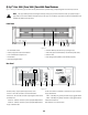
Refer to Figure 9
• Phillips screwdriver
• ESD grounded wrist strap
• 1/4” hex driver/socket (not shown) for replacing Q-Sys I/O Cards in positions C or D.
CAUTION!: An ESD grounded wrist strap must be worn throughout the remove and
replace procedure. The end of the wrist strap should be connected to an unpainted
surface on the product chassis such as the ground stud.
1. Disconnect the AC mains power cord from the Q-Sys I/O Frame.
2. Connect and put on the ESD grounded wrist strap.
3. Remove the sheet metal screws securing the lid to the Q-Sys I/O Frame chassis. Remove the lid by
lifting it approximately 1" at the rear of the chassis while sliding it back from the front.
NOTE: To remove an I/O Card in position C or D, you must first remove the appropriate
card above it in position A or B. The following steps apply to both top and bottom cards.
4. Locate the I/O Card to be replaced and, except for the Blank Card, remove the ribbon cable from the
card by gently pushing outward on the cable ejector tabs. (Figure 10) The connector should be free
of the socket.
5. Remove the two screws securing the I/O Card mounting bracket to the rear of the chassis. Remove
the bracket. (Figure 11)
6. Remove the I/O Cards:
a. For cards in positions A or B, remove the four Phillips head screws securing the card to the
standoffs. Remove the card. If you are not replacing a card in position C or D, skip to step 7.
b. For cards in positions C or D, perform step 6.a, then remove the four hex standoffs securing the
lower card, and remove the card.
7. Install the new I/O Card by reversing steps 5 and 6. Be sure to align and secure the rear panel
mounting bracket before tightening the hex standoffs or card-securing screws. If you are replacing
a card in positions C or D, complete step 8 now, and then install the upper card and
repeat step 8 for the upper card.
8. Reconnect the ribbon cable to the I/O Card, by aligning the tab on the cable connector housing with
the key on the card connector as shown in Figure 12. Gently push down on the cable connector
housing to seat the cable into the card connector. When properly seated, the cable ejectors will lock
in place with the thumb tabs upright.
9. When replacing the Blank Card with an I/O Card, the new ribbon cable must also be attached to the
I/O Frame main board. To do this, locate the main board audio connectors (Figure 13) , Then locate
the appropriate card position indicator on the main board for the card being replaced (A, B, C or D).
Attach the ribbon cable in the same manner as the I/O Card, ensuring that the cable connector tab
is aligned with the main board connector key and that the cable is properly seated with the ejector
tabs in their locked position.
10. Replace the I/O Frame lid and secure the sheet metal screws.
— Figure 9 —
— Figure 10 —
— Figure 11 —
— Figure 12 —
— Figure 13 —