
Owner's Manual


10
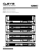
Q-Sys™ Core 1000 | Core 3000 | Core 4000 Panel Features
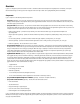
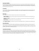
— Figure 4 and — Figure 5 show the Q-Sys Core front and rear panel features for a product having a simple configuration of one blank I/O Card slot.
NOTE: The Q-Sys hardware products are configured at the QSC factory per your order. At the time of order, you specify the type of
Q-Sys Audio I/O Card to be installed in the Audio I/O bay on the Q-Sys Core. In addition, Q-Sys Audio I/O Card Kits are available for field
installation by qualified service personnel.
Front Panel
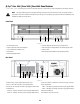
Rear Panel
— Figure 4 —
1 2 3 4
5
6
7
8
9
1. SD Card Reader Socket
2. Audio I/O Signal and Card Present Indicators
3. 240 x 64 Monochrome Graphics LCD
4. Exhaust Vents
5. Next Page Navigation Button
6. Device ID Button (locates device in Q-Sys Designer GUI)
7. Status LED (reports network health, ID and firmware update status)
8. Power On LED
9. Clear Settings Paperclip Button (resets network properties)
10. Audio I/O Bay – accepts optional Q-Sys audio I/O cards
11. RS-232 – DE-9 male connector for serial communications
12. Video Out – HD-15 female connector accepts diagnostic VGA monitor
13. Auxiliary Ports
AUX A Set – USB host connector x2, RJ45 10/100/1000 Mbps Ethernet
AUX B Set – USB host connector x2, RJ45 10/100/1000 Mbps Ethernet
14. GPIO A and GPIO B – female DA-15 connectors for Q-Sys control I/O
15. Q-Sys Network Port
LAN A – 1000 Mbps only, primary connection to Q-Sys gigabit network
LAN B – 1000 Mbps only, backup connection to Q-Sys gigabit network
16. Reserved for Future Use
17. AC Main Inlet – IEC male connector
— Figure 5 —
10 11 12 13 14 15 16 17