
Owner's Manual


11
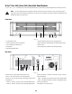
Q-Sys™ I/O Frame Panel Features
— Figure 6 and — Figure 7 show the Q-Sys I/O Frame front and rear panel features for a product having a sample configuration of two Mic / Line Input
Cards and two DataPort I/O Cards.
NOTE: The Q-Sys hardware products are configured at the QSC factory per your order. At the time of order, the you specifies the type
of Q-Sys Audio I/O Card to be installed in each of the four rear panel audio I/O bays on the Q-Sys I/O Frame. In addition, Q-Sys Audio
I/O Card Kits are available for field installation by qualified service personnel.
Front Panel
Rear Panel
— Figure 6 —
1 2
3
4 5
7
8
6
1. Fan Exhaust Vents
2. Audio I/O Signal and Card Present Indicators
3. 240 x 64 Monochrome Graphics LCD
4. Next Page Navigation Button
5. Device ID Button (locates device in GUI)
6. Reset Network Properties Paperclip Button
7. Status LED (reports network health, ID and firmware update status)
8. Power On LED
— Figure 7 —
9
10 11
12 13
9. Configurable Audio I/O Bays
10. GPIO Interface (control I/O) (see Page 12)
11. RS-232 Serial Control Interface
12. Dual Gigabit Network Interfaces for Q-Sys LANs
13. AC Main Inlet – IEC male connector