
Owner's Manual


12
Q-Sys™ I/O Card Install/Uninstall Procedure
Card installation should only be done by a trained and qualified technician.
Tools needed: Phillips screwdriver | ESD wrist strap (ground strap)
1. An ESD wrist strap must be worn throughout the install/uninstall procedure. The end of the wrist
strap should be connected to an unpainted surface on the product chassis such as the ground stud.
2. Disconnect the AC mains power cord.
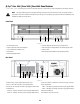
3. Remove the sheet metal screws securing the lid to the Q-Sys I/O Frame chassis. Remove the lid by
lifting it approximately 1" at the rear of the chassis and sliding it back from the front. (— Figure 8)
4. Locate the Q-Sys I/O Card to be replaced. Remove the ribbon cable from the card by gently lifting
up on the plastic ribbon cable locking tab on the connector at the edge of the card. Ensure that the
cable edge does not get damaged. (— Figure 9)
5. Remove the two screws securing the Q-Sys I/O Card mounting bracket to the rear of the chassis.
Remove the bracket. (— Figure 10)
NOTE: Note: in order to remove an I/O Card in position C or D, first uninstall the
appropriate card above in position A or B.
6. For Q-Sys I/O Cards in positions A or B, remove the four Phillips head screws securing the card and
remove the card. For cards in positions C or D, remove the card above, then remove the four hex
standoffs and remove the card to be replaced.
7. Install the new Q-Sys I/O Card by reversing steps 4 through 6. Be sure to align and secure the rear
panel mounting bracket before the hex standoffs or card-securing screws are completely tightened.
8. Reattach the ribbon cable to the Q-Sys I/O Card. Make sure that the edge of the ribbon cable is
properly aligned with the connector mating surface. The blue band on the ribbon cable should be
facing upward. Engage the ribbon cable locking tab on the connector by gently pressing down on
the locking tab.
9. If replacing a blank Q-Sys I/O Card with an audio I/O Card, the ribbon cable in step 8 must also be
connected to the Q-Sys I/O Frame main circuit board. To do this, locate the connector corresponding
to the appropriate I/O Card position (connector labels on the main board match the I/O Card
positions printed on the product rear panel). Insert the ribbon cable into the main board connector
by first lifting the plastic ribbon cable locking tab on the connector. Then align the ribbon cable with
the connector contacts and insert the edge of the ribbon cable into the connector slot. (— Figure
11) The blue band on the ribbon cable should face the system power supply. Make sure the ribbon
cable locking tab on the connector is engaged by holding the ribbon cable in place and gently
pressing down on both sides of the locking tab simultaneously until the tab locks in place. (— Figure
11)
10. Replace the Q-Sys I/O Frame lid and secure the sheet metal screws.
— Figure 8 —
— Figure 9 —
— Figure 10 —
— Figure 11 —
— Figure 12 —