675 MacArthur Blvd., Costa Mesa, CA, 92626 USA Main Number (714) 754-6175 or toll free (USA only) (800) 854-4079 Customer Service(714) 957-7150 or toll free (USA only) (800) 772-2834 HPR Series Powered Loudspeaker Products User Manual HPR153F HPR152F HPR151W HPR181W 15-inch three-way 15-inch two-way 15-inch subwoofer 18-inch subwoofer *TD-000212-01* TD-000212-01 rev.
Important Safety Precautions & Explanation of Symbols Install in accordance with QSC Audio Product's instructions and under the supervision of a licensed Professional Engineer. WARNING! CAUTION: TO REDUCE THE RISK OF ELECTRIC SHOCK, DO NOT REMOVE THE COVER. NO USER-SERVICEABLE PARTS INSIDE. REFER SERVICING TO QUALIFIED PERSONNEL.
Introduction Congratulations and thank you for your purchase of this professional, powered loudspeaker product. To get the most from your investment, we recommend you review all the information provided in this User Manual. The HPR self-powered loudspeakers provide excellent sound quality, durable construction and clean, efficient, on-board amplification. Amplifiers are matched to the drivers with active equalization and precise crossover control.
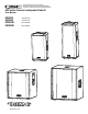
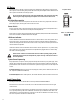
HPR151W Features HPR181W Features 1- Pole Cup 2- Handles (2 each) 3- Grill 4- Power Amplifier 5- Slip-resistant Feet (4 each) 6- Casters (HPR181W only) Full Range Amplifier Detail 1- Input and Output Connector(s) 2- Gain Control 3- Power, Signal, and Clip LED Indicators 4- Front LED Switch 5- 100 Hz Low-Cut Filter Switch (Full Range Only) 4 Subwoofer Amplifier Detail 6- Power Switch 7- Circuit Breaker 8- Serial Number Plate 9- IEC Power Inlet 10- Phase switch (Subwoofer Only)
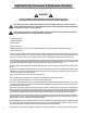
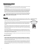
Installation HPR152F WARNING! Do not use a loudspeaker support pole longer than 26” (660mm) when supported by the HPR151W or HPR181W subwoofer. Do not rig, fly or suspend this loudspeaker product! Before placing or installing any speaker product, inspect all hardware, suspension, cabinets, transducers, brackets and associated equipment for damage. Any missing, corroded, deformed, or non-factory component could significantly reduce the strength of the installation, placement or array.
AC Mains Connect AC power to the IEC socket on the back of the amplifier by locating the IEC connector-end of the AC power cord and inserting it fully into the IEC inlet on the power amplifier module. NOTE: Turn off the AC power switch before connecting AC power. AC power switch The correct AC line voltage is shown on the serial number label, on the rear panel. Connecting to the wrong line voltage may damage the amplifier or increase the risk of electric shock.
Input Connections (continued) HPR152F and HPR153F: Insert the male XLR input into the jack marked FULL RANGE LINE IN. Ensure the connector is fully seated. HPR151W and HPR181W: Insert the left channel’s XLR input into the left channel’s (L) FULL RANGE LINE IN connector. Insert the right channel’s XLR connector into the right channel’s (R) FULL RANGE LINE IN connector. If a single input signal is used, plug into either the L (left) or R (right) channel’s input.
Output Connections (continued) HPR151W and HPR181W FULL RANGE LINE OUT: Use the outputs marked FULL RANGE LINE OUT (Left and/or Right) when connecting to down-stream powered loudspeakers which accept full-range audio or have their own filtering. 100 Hz LOW-CUT: Use the outputs marked 100 Hz LOW-CUT OUT (L and/or R) when connecting to downstream powered loudspeakers that have no low-frequency filtering but the low-frequency roll-off is desired.
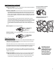
100 Hertz Low-Cut Filter Switch (HPR152F and HPR153F) Below the LED indicators is a small recessed slide-switch that enables or disables a 100 Hertz low-cut filter. 100 Hertz low-cut filter switch off and on positions Filter OFF (Full Range) Turn the filter OFF when using without subwoofers or dedicated low-frequency enclosures. Filter ON (100 Hz Low-Cut) Turn the filter ON when using with optional subwoofers or low-frequency systems.
SIGNAL Indicator LED The green SIGNAL indicator alerts the user to the presence of an input signal to the HPR loudspeaker. Normal Indication The green SIGNAL indicator illuminates when the input signal exceeds -25 dB. If No Indication Check Gain settings and increase gain if necessary. Check input connections and audio source for signal. If the red LIMIT LED illuminates, refer to the LIMIT indicator section, below.
Application Example #1 Application Example #1 physical diagram. This example shows a two-channel (stereo) setup utilizing two top-boxes. Audio signals for the Left and Right channels are supplied by the mixer console. This signal source can be just about any variable-output level audio source, such as DJ mixers, professional CD players, or computer-based audio signal sources.
Application Example #2 Application Example #2 physical diagram. This example shows a two-channel (stereo) setup utilizing one subwoofer and two top-boxes. Audio signals for the Left and Right channels are supplied by the mixer console. This signal source can be just about any variable-output level audio source, such as DJ mixers, professional CD players, or computer-based audio signal sources. Audio output from the mixer is connected to the subwoofer’s Left (L) and Right (R) channels.
Application Example #3 This example shows a two-channel (stereo) setup utilizing two subwoofers and two top-boxes. Application Example #3 physical diagram. Audio signals for the Left and Right channels are supplied by the mixer console. This signal source can be just about any variable-output level audio source, such as DJ mixers, professional CD players, or computer-based audio signal sources. Audio output from the mixer is connected to the subwoofer input of each channel.
Application Example #4 This example shows a two-channel (stereo) setup utilizing two subwoofers and multiple top-boxes. This is the same as Application Example #3 except an additional top-box has been added to each channel (and more could be added). Channel 2 or Right Channel Channel 1 or Left Channel To connect to additional top-boxes, connect a cable from the last top box’s FULL RANGE LINE OUT connector to the next top-box’s FULL RANGE LINE IN connector.
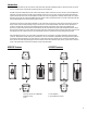
Dimensions, HPR152F Dimensions, HPR153F 15
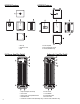
Dimensions, HPR151W Dimensions, HPR181W 16
Specifications, Full Range Models HPR152F HPR153F Frequency Response, ±6dB 53-18k Hz 42-19k Hz Frequency Range, -10dB limit 50-20k Hz 38-20k Hz Maximum Peak SPL 135dB 133dB Nominal coverage, H x V 90°x60° 90°x40° Directivity Index 9.4 11.1 Directivity Factor 8.7 12.9 Transducer Description 15” (381mm) transducer with 3” (76mm) voice coil 1” (25mm) throat compression driver 15” (381mm) transducer with 3” (76mm) voice coil 6.
Specifications, Subwoofer Models HPR151W HPR181W Frequency Response, ±6dB 47-110 Hz 42-110 Hz Frequency Range, -10dB limit 43-140 Hz 39-140 Hz Maximum Peak SPL 133dB 134dB Nominal coverage, H x V Not applicable (N/A) Not applicable (N/A) Directivity Index 0 0 Directivity Factor 1 1 Transducer Description 15” (381mm) transducer with 3” (76mm) voice coil 18” (457mm) transducer with 4” (102mm) voice coil Amp Power 700 Watts 700 Watts Input Sensitivity 0.775 Vrms (+0dBu) 0.
Notes: 19
Warranty (USA only; other countries, see your dealer or distributor) Disclaimer QSC Audio Products, Inc. is not liable for any damage to amplifiers or any other equipment that is caused by negligence or improper installation and/or use of this loudspeaker product. QSC Audio Products 3 Year Limited Warranty QSC Audio Products, Inc.