675 MacArthur Blvd.
IMPORTANT SAFETY PRECAUTIONS Install in accordance with QSC Audio Product's instructions and under the supervision of a licensed Professional Engineer. WARNING! Before placing, installing, rigging, or suspending any speaker product, inspect all hardware, suspension, cabinets, transducers, brackets and associated equipment for damage. Any missing, corroded, deformed, or non-load rated component could significantly reduce the strength of the installation, placement or array.
Introduction The Installation Line Array (ILA) is a high performance line array system designed for the needs of Houses of Worship, Performing Arts facilities and a multitude of other venue types. The current ILA family is composed of the WL2082-i line array element, WL115-sw subwoofer, FB2082-i array frame, PB2082-i pull-back bar, EB2082-i extension bar, and GS115-sw Ground Stack Kit. Installation Line Arrays may be used in outdoor applications where the system is somewhat protected from the elements.
Introduction (continued) WL115-sw The WL115-sw subwoofer extends the system’s low-frequency capability to 35 Hz. with a compact fourth-order bandpass enclosure. Its ceramic magnet, 4” voice coil, 15” transducer provides 650 watt continuous power handling capability. Many users of line array systems have found that suspending the subwoofers with the array provides audible benefit. Additionally, many venues lack physical space for floor-mounted subs.
Introduction (continued) Figure 3: FB2082-i Array Frame 1- Shackle holes (accept 3/4” (20 mm) screw pin anchor shackle) 2- Center support bar 3- Rigging plates 4- Rigging plate retaining bolts 5-Rigging plate attachment holes Use only shackle holes for suspension of array! Figure 4: PB2082-i Pull Back Bar 1- Shackle hole (accepts 5/8” (16 mm) screw pin anchor shackle) 2- Rigging plate attachment holes 3- Rigging plates 4- Rigging plate retaining bolts Use only shackle hole for suspension of array! Figur
Introduction (continued) Figure 6: GS115-sw Ground Stack Kit 1- Rail 2- Rubber foot 3- Attachment holes Rigging the Installation Line Array Rules for Suspension •Correct use of all suspension hardware and components is imperative in sound system rigging and deployment. •Always calculate suspended loads before lifting to ensure suspension components and hardware are used within their respective load limits.
Rigging the Installation Line Array (continued) Table 1: ILA Working Load Limits Component Weight 7:1 Design Factor 10:1 Design Factor 12:1 Design Factor EB2082-i Extension Bar 38 lb (17.3 kg) 1714 lb (779.2 kg) 1200 lb (545.5 kg) 1000 lb (454.5 kg) FB2082-i Array Frame 17 lb (7.7 kg) 740 lb (336.4 kg) 518 lb (235.5 kg) 432 lb (196.2 kg) PB2082-i Pull Back Bar 6 lb (2.7 kg) 423 lb (192.2 kg) 296 lb (134.5 kg) 247 lb (112.1 kg) WL2082-i Loudspeaker 37 lb (16.8 kg) 634 lb (288.
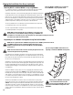
Figure 8:PB2082-i under WL2082-i attached to FB2082-i. Rigging the Installation Line Array (continued) Pull-Back Bar If using the pull-back bar, attach to the bottom enclosure at the bottom-most splay angle adjustment holes at the rear of the rigging plate by inserting the cap-head shoulder bolt through the mated pieces and threading the lock nut (nylock) on the inside edge of the plates. Use a 5/8” (16 mm) shackle to attach to the pull-back bar shackle hole located in the center of the main bar.
Figure 11: WL115-sw attached to FB2082-i. Rigging the Installation Line Array (continued) 3- Lower the array frame onto the enclosure, carefully aligning the rigging straps, and attach the top enclosure to the array frame by installing the ball-lock pins or M8 bolts. Before lifting, ensure the audio connection to the enclosures are correct and functioning. NOTE: When attaching one WL115-sw to another WL115-sw, you must use the supplied ball-lock pins.
Rigging the Installation Line Array (continued) Attaching WL115-sw behind WL2082-i array using EB2082-i Figure 15: EB2082-i with WL115-sw suspended at rear and WL2082-i array suspended at front. It is sometimes necessary to suspend the subwoofers behind the main array. Extreme splay angles may result in physical interference with rear-flown subwoofers.
WL2082-i Controls and Connections Figure 17: MODE selection switch. MODE Selection Switch BI AMP: When set to BI AMP, an internal shading network removes the mid-frequencies from one of the lowfrequency drivers. The BI AMP HORIZONTAL SHADING switch will select which transducer is shaded. TRI AMP: Shading network is NOT applied (shading must be provided by upstream signal processing). The Bi Amp Mode Horizontal Shading selector switch is not functional in tri amp mode.
WL115-sw Connections Figure 20: WL115-sw Input Plate Input Connections The WL115-sw input connectors are a pair of Neutrik NL8's wired in parallel. See Table 3 or the WL115-sw Input Plate for connector pinout. Note pin numbers 2+, 2-, 3+, 3-, 4+, and 4- are wired straight through from one connector to the other. This accommodates using one input cable assembly (where appropriate) for subwoofer and full range loudspeaker connections. Additionally, pin numbers 1+ and 1- of both NL8s are wired in parallel.
WL2082-i Specifications Frequency Response: 80 - 20,000 Hz (+/- 3 dB) Frequency Range: 68 - 22,000 Hz (-10 dB) Maximum SPL (continuous/peak): HF: 126/132 dB Nominal Coverage (-6 dB included): Horizontal: 140 degrees (500 Hz to 3.2 kHz)Vertical: dependant on cumulative splay angle LF: 122/128 dB Transducers: High Frequency: Dual 50W, 8 Ohm 1 inch exit, 1.
WL115-sw Specifications Frequency Response: 37 - 107 Hz (+/- 3 dB) Frequency Range: 35 - 112 Hz (-10 dB) Maximum SPL (continuous/peak): 124 dB/130 dB Transducer: 650W, 8 Ohm 15 inch woofer, 4 inch voice coil, ceramic magnet assembly Recommended Crossover Frequency: 35 - 85 Hz Input Sensitivity: 96 dB Weight: Net: 111 lb (50.4 kg) Enclosure: 0.708 inch (18 mm) Baltic birch plywood, paint finish. Connectors: Two (2) Neutrik NL8 in parallel (wired as shown in Table 3) Shipping: 121 lb (55.
EB2082-i Specifications Material: Aluminum 6061-T6 Finish: Black powder coat (White optional) Working Load Limit Information: Component Weight 7:1 Design Factor 10:1 Design Factor 12:1 Design Factor EB2082-i Extension Bar 38 lb (17.3 kg) 1714 lb (779.2 kg) 1200 lb (545.5 kg) 1000 lb (454.
PB2082-i Specifications Material Aluminum 6061-T6 Finish Black powder coat (White optional) Working Load Limit Information: Component Weight 7:1 Design Factor 10:1 Design Factor 12:1 Design Factor PB2082-i Pull Back Bar 6 lb (2.7 kg) 423 lb (192.2 kg) 296 lb (134.5 kg) 247 lb (112.1 kg) GS115-sw Specifications 16 Material Aluminum 6061-T6 Finish Black powder coat (White optional) Weight 5 lb (2.
How to Contact QSC Audio Products Mailing address: QSC Audio Products, Inc. 1675 MacArthur Boulevard Costa Mesa, CA 92626-1468 USA Telephone Numbers: Main Number (714) 754-6175 Sales & Marketing (714) 957-7100 or toll free (USA only) (800) 854-4079 Customer Service (714) 957-7150 or toll free (USA only) (800) 772-2834 Facsimile Numbers: Sales & Marketing FAX (714) 754-6174 Customer Service FAX (714) 754-6173 World Wide Web: www.qscaudio.com E-mail: info@qscaudio.com service@qscaudio.