
User's Manual


11
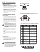
WL2082-i Controls and Connections
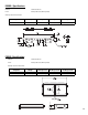
MODE Selection Switch
BI AMP: When set to BI AMP, an internal shading net-
work removes the mid-frequencies from one of the low-
frequency drivers. The BI AMP HORIZONTAL SHADING
switch will select which transducer is shaded.
TRI AMP: Shading network is NOT applied (shading
must be provided by upstream signal processing). The
Bi Amp Mode Horizontal Shading selector switch is not
functional in tri amp mode. Connect to the Speakon as
shown for tri amp.
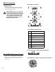
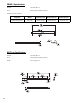
BI AMP MODE HORIZONTAL SHADING
Selection Switch
The BI AMP MODE HORIZONTAL SHADING selection
switch is only functional in bi amp mode. This switch
determines which low-frequency transducer receives
only low-frequency program material (shading). The un-
shaded transducer receives low- and mid-frequency
program material. This allows switch position selection
for use as either “house left” or “house right”, without
the need to flip boxes.
NOTE: LEFT and RIGHT markings on the BI
AMP HORIZONTAL SHADING SWITCH apply
to the enclosure as viewed from the rear (i.e.
looking at the Input Plate with the text prop-
erly oriented).
LEFT: Use this setting to steer coverage to the left (as
viewed from behind the arrays, looking toward the
audience).
RIGHT: Use this setting to steer coverage to the right
(as viewed from behind the arrays, looking toward the
audience).
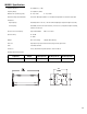
Input Connections
The WL2082-i input connectors are a pair of Neutrik
NL8's wired in parallel. Connections for biamp and tri-
amp vary, see Table 2 or the pinout table on the
WL2082-i input plate (Figure 19).
The WL2082-i loudspeaker is not equipped
with a crossover network. All signal pro-
cessing must be done before connecting
audio power to the loudspeaker. Do not con-
nect full-range audio to the high-frequency
transducer or damage may result!
LF1LF2
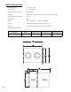
Table 2: WL2082-i Connector Pinout for BI AMP and TRI AMP Mode
PIN BI AMP TRI AMP
1+
Through Through
1-
Through Through
2+
No Connection Left Low Frequency
Transducer + (16 Ohms)
2-
No Connection Left Low Frequency
Transducer - (16 Ohms)
3+
Left and Right Low Fre-
quency Transducers in
Parallel + (8 Ohms)
Right Low Frequency
Transducer + (16 Ohms)
3-
Left and Right Low Fre-
quency Transducers in
Parallel - (8 Ohms)
Right Low Frequency
Transducer - (16 Ohms)
4+
High Frequency Trans-
ducer + (16 Ohms)
High Frequency Trans-
ducer + (16 Ohms)
4- High Frequency Trans-
ducer - (16 Ohms)
High Frequency Trans-
ducer - (16 Ohms)
Figure 17: MODE selection switch.
Figure 18: BI AMP MODE HORIZONTAL SHADING selection switch.
Figure 19: Pinout table as printed on WL2082-i input plate label