
User's Manual

20
USE- AC Power Switch and LED Indicators
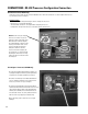
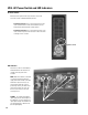
LED Indicators
Each Processor has two LED indicators,
PWR and SIGNAL. The indicators are
located on the rear panel of the
215PCM.
PWR- When the 215PCM is connected
to a properly rated and working AC
supply circuit and is turned on, the blue
PWR LED on each of the Processors
will illuminate. When the system is
powered up correctly, two blue Power
LED’s will be visible; one on the Top
Box Processor and one on the Sub-
woofer processor.
SIGNAL- The SIGNAL LED indicates
input signal presence and strength. It is
dual brightness to give an indication of
input signal strength. The SIGNAL LED
will illuminate dimly at -40 dB. At -20
dB it will light brightly.
LED indicators.
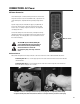
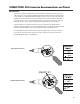
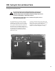
AC Power Switch
Above and to the right of the AC entry connector is the Power
switch. The switch is labeled POWER ON, above it.
To turn the power on: Press in on the upper portion of the
rocker switch. Both DSP-3’s blue Power indicators should
illuminate after a brief amplifier startup sequene.
To turn the power off: Press in on the bottom portion of the
rocker switch. It may take a few moments for the Power LED’s
to extinguish. This is normal.
Power switch.