K.2 Series ® User Manual K8.2 – 105° 2000 W active 8” (200 mm) 2-way loudspeaker system K10.2 – 90° 2000 W active 10” (250 mm) 2-way loudspeaker system K12.2 – 75° 2000 W active 12” (300 mm) 2-way loudspeaker system K.2 Series TD-000523-01-C *TD-000523-01* K.2 Series K.
EXPLANATION OF SYMBOLS The term “WARNING!” indicates instructions regarding personal safety. If the instructions are not followed the result may be bodily injury or death. The term “CAUTION!” indicates instructions regarding possible damage to physical equipment. If these instructions are not followed, it may result in damage to the equipment that may not be covered under the warranty. The term “IMPORTANT!” indicates instructions or information that are vital to the successful completion of the procedure.
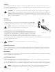
14. The appliance coupler, or the AC Mains plug, is the AC mains disconnect device and shall remain readily operable after installation. 15. Adhere to all applicable, local codes. 16. To prevent electrical shock, the power cord shall be connected to a mains socket outlet with a protective earthing connection. 17. Consult a licensed, professional engineer when any doubt or questions arise regarding a physical equipment installation. 18.
RoHS Statements These products are in compliance with European Directive 2011/65/EU – Restriction of Hazardous Substances (RoHS). These products are in compliance with “China RoHS” directives per GB/T26572.
Features 7 K8.2 1 1. ABS enclosure 4 1 6 6 4 2. Steel grille 11 3. Front power LED 4. Cast aluminum handle 2 5. Power module 7 6. M10 installation points 5 7 11 7. M5 yoke-attachment points K.2 Series 8. 7.5° Downward-tilt pole socket 3 9. Vertical pole socket 11 8 9 10. Pull-back ring 11. Slip-resistant feet for floor monitor applications 10 11 12. Angled back for use as a stage monitor 11 12 10 — Figure 1 — K10.2 1. ABS enclosure 7 2. Steel grille 1 6 3.
K12.2 1. ABS enclosure 7 2. Steel grille 1 6 3. Front power LED 1 4 6 4 4. Cast aluminum handles 11 5. Power module 6. M10 installation points 2 7. M5 yoke attachment points 7 8. 7.5° Downward-tilt pole socket 7 7 5 4 11 9. Vertical pole socket 10. Pull-back ring K.2 Series 11.
Applications The K.2 Series has been primarily designed for portable audio reinforcement. This includes a variety of uses in reinforcement for entertainers and presenters. All are designed to perform well on their own in full-range audio. They can be used singly, in stereo pairs or in distributed or delayed systems. They perform extraordinarily well as both main reinforcement systems and as floor monitors as shown in Figure 4.
Deployment The K.2 Series loudspeakers were designed to sit on the floor, stage, a subwoofer enclosure, be suspended, or be pole mounted on a 35 mm diameter loudspeaker support pole. If you are going to pole-mount on a subwoofer, refer to the chart below for specifics. K8.2 K10.2 K12.2 WARNING!: Do not use a loudspeaker support pole longer than the lengths specified in the table below when supported by a subwoofer. Subwoofers K.2 Series KS212C KW181 Maximum 36 in (914 mm) KSUB K8.
Cooling This is a powered loudspeaker containing an internal power amplifier that produces heat. Allow a minimum of 6" (152 mm) clearance at cabinet back for convection cooling. Keep anything that might restrict airflow away from the rear of the enclosure (i.e draperies, walls, etc.) CAUTION!: Do not install enclosures with their rear panels exposed to direct sunlight. Direct sunlight will heat the amplifier module and reduce its ability to produce full output. Install sunshades if needed.
System Power Sequencing Proper power turn on/turn off sequencing can help to prevent unexpected sounds from being produced by the system (pops, clicks, thumps). Always follow the rule that speakers are “last on, first off”. Power On Sequence: Bring the output level control of the mixer (or other audio source) feeding your speakers to its minimum position. Turn on all source devices (CD players, mixers, instruments), turn on subwoofer, then turn on the “topboxes” ( K8.2, K10.2 and K12.2).
Inputs The K.2 Series amplifier has three separate inputs; two combination XLR / 1/4” Phone Jack (Inputs A and B) and one 1/8” (3.5 mm) TRS jack (Input C). Refer to Figure 12 1. Input A a. SIG LED – When illuminated (green), it indicates a signal is present. If this LED is not illuminated, the input signal is missing or too low to detect. 2a 2b 2c 3a 3b 1a 1b 1c 3c 4 5 1d 2d b. MIC LED – When illuminated (yellow) it indicates the input — Figure 12 — is configured to accept a microphone input.
4. LIMITER LED – Illuminates (red) when the built-in limiter is activated to protect and avoid damage to the amplifier or loudspeaker. If the signal level at any frequency is too high, or the amplifier is too hot, the limiter is activated and the LED is illuminated. 5. POWER LED – Illuminates (blue) when power is applied to the unit and the ON/OFF switch is in the ON position.
Outputs 1. Channel B pass-through output connector. The signal here is the same as the input signal on Channel B. Use this to daisy-chain loudspeakers or to provide the signal to other audio equipment. 2. Channel A pass-through output connector. The signal here is the same as the input signal on Channel A. Use this to daisy-chain loudspeakers or to provide the signal to other audio equipment. 1 2 3 3. MIX OUT (Post Gain) output XLR is a mix of Channels A, B, — Figure 17 — and C.
Menu Map INPUT A LINE MIC* INPUT B HI-Z LINE SUB MENU PRESET DELAY PEQ BAND 1 PEQ HIGH SHELF PEQ LOW SHELF PEQ BAND 2 SETTINGS EQ EQ RESET EQ IN/OUT SAVE SCENES FIRMWARE VERSION RECALL SCENES FACTORY RESET LED CONTRAST — Figure 19 — Menu Listing INPUT A: Select the sensitivity of input A INPUT A LINE Use with mixers and other sources that have high-level outputs.
PRESETS Select a pre-programmed EQ and dynamic processing setting for specific applications Factory Presets Example SUB MENU FACTORY PRESETS AC GUIT/VOX BASS AMP HAND MIC Use the Selector knob to scroll (up or down) to the Preset you wish to recall.
DELAY 100 Hz K – KW – KLA Applies a 100 Hz High Pass Filter (HPF) (For use with a K-SUB, KW Sub, or KLA Sub) 125 Hz Applies a 125 Hz High Pass Filter (HPF) Adjust the signal delay for rear fill and similar applications. DELAY Delay EQ 0 –100 milliseconds, 0 – 113 feet, 0 – 34 meters All units of measure change together when the Selection knob is turned. ms FEET METERS Adjust the 4-band, parametric equalizer EQ Example SETTINGS 1.00 1.13 0.43 EQ HIGH EQ1 EQ2 LOW EQ IN dB -2.0 1.13 0.43 1.
Hookup Diagrams Two Loudspeakers Daisy-chained — Figure 20 — Typical Stereo System LEFT RIGHT — Figure 21 — TD-000523-01-C 17
Standalone System MIC HI-Z — Figure 22 — TD-000523-01-C 18
Dimensions K8.2 Loudspeaker 10.6 in 269 mm 11 in 280 mm 17.5 in 445 mm 17.7 in 449 mm 17.7 in 449 mm K.2 Series 11 in 280 mm 10.
K10.2 Loudspeaker 11.8 in 300 mm 12.6 in 320 mm 20.0in 515 mm 20.4 in 519 mm 20.4 in 519 mm K.2 Series 11.8 in 300 mm 12.
K12.2 Loudspeaker 13.8 in 350 mm 14 in 356 mm 23.5 in 598 mm 23.7 in 602 mm 23.7 in 602 mm K.2 Series 14 in 356 mm 13.
Specifications K8.2 K10.2 K12.2 Configuration: Multi-purpose, 2-way powered loudspeaker LF Transducer: 8” (203 mm), cone HF Transducer: 1.4” (35.
® Mailing Address: QSC, LLC 1675 MacArthur Boulevard Costa Mesa, CA 92626-1468 USA Telephone Numbers: Main Number: 714-754-6175 Sales & Marketing: 714-957-7100 or toll free (USA only) 800-854-4079 Customer Service: 714-957-7150 or toll free (USA only) 800-772-2834 Facsimile Numbers: Sales & Marketing FAX: 714-754-6174 Customer Service FAX: 714-754-6173 World Wide Web: qsc.com E-mail: info@qsc.com service@qsc.