
User manual


11
TD-000368-01-A
Inputs
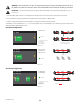
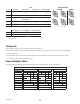
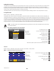
Connect the Audio Inputs
— Figure 10 — — Figure 11 —
1
3
2
1
Ground
3
Negative
2
Positive
Balanced
Inputs
— Figure 12 —
1+3
Ground
2
Positive
Unbalanced
Inputs
1
3
2
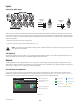
There are four female XLR connectors labeled 1 through 4 that provide the audio inputs to the PLD amplifi ers. A single input can be routed to one
or a combination of outputs. You can use from one to four of the inputs. The inputs are 10 kΩ balanced or unbalanced, with a selectable sensitivity
of either +4 or +14 dBu. There are four male XLR connectors in parallel with the four female connectors. The male XLRs are for daisy chaining to the
inputs of other amplifi ers.
1. Make sure your audio source devices are powered off.
2. Connect the input source XLRs to the four female XLRs. (Figure 10)
NOTE:
The PLD Series has the capability of routing the inputs to different outputs. Be sure that the connections you make here match
the confi guration of the amplifi er.
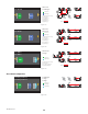
USB (Optional)
The USB cable (supplied) connects to a Mac or PC for use with the Amplifi er Navigator software. You can update the amplifi er fi rmware, save and
deploy confi guration fi les, and more. Refer to the Amplifi er Navigator online help for details.
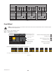
Outputs
The PLD amplifi ers have four confi gurable outputs. You can set the power, combine outputs (bridged and parallel), and adjust the DSP for each
output. When the output confi guration of the amplifi er changes, the output connections, controlled by relays, change accordingly. Use the diagrams
shown in Figure 14 thru Figure 22 as a reference for wiring the loudspeakers.
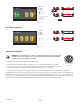
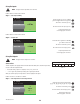
Select the Output Confi guration
The fi rst step is to select a Preset based on the loudspeakers being connected to the amplifi er. You can use a factory preset, and then adjust the
parameters as needed, then save the confi guration as a user-defi ned preset. In addition, you can use the "Power Distribution Charts" on page 15
to create presets from the ground up. When the confi guration is changed, all four channels are automatically muted.
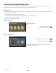
— Figure 13 —
F1: A B C D
F7: ABC D
1
ABC
4
D
Input number
Sub-woofer
Mid-Frequency
Full Range
High-Frequency
Low-Frequency
Current Configuration
Selected Configuration
Input number
Output Configuration
Frequency Range color
Frequency Range Color Codes