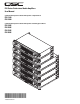
PLX Series Professional Audio Amplifiers User Manual 4-ohm minimum impedance models with Speakon® output terminals: PLX 1104 PLX 1804 2-ohm minimum impedance models with Speakon and binding post terminals: PLX 1802 PLX 2502 PLX 3102 PLX 3602 *TD-000214-00* TD-000214-00 Rev.
Important Safety Precautions & Explanation of Symbols 1- Read these instructions. 2- Keep these instructions. 3- Heed all warnings. 4- Follow all instructions. 5- WARNING: To prevent fire or electric shock, do not expose this equipment to rain or moisture. Do not use this apparatus near water. 6- Clean only with a dry cloth. 7- Do not block any ventilation openings.
Introduction Thank you for purchasing this QSC power amplifier. Please read the following directions to obtain the best results. This manual covers all models of the PLX series. Illustrations show the PLX 1804 to be representative of the PLX 1104 and 1804 models, while the PLX 3602 illustration is representative of the PLX 1802, PLX 2502, PLX 3102, and PLX 3602 models.
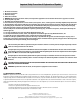
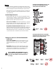
Rear Panel 1- Input Configuration switch 2- 1/4-inch TRS input connectors 3- XLR female input connectors 4- Low Frequency Filter switches 5- Speakon output connectors 6- Binding post output connectors 7- Cooling air inlet vents 8- Clip Limiter switch 9- Serial number plate 10- IEC-type AC mains inlet 11- Circuit breaker, resettable Rack Mounting Use four screws and washers to mount the amplifier to the equipment rack rails.
Cooling Air flows from the rack, into the back of the amplifier, and out the front. This keeps the rack cool. The fan automatically runs faster when the amp is working hard. Air flow in QSC amplifiers: Cool air is drawn into the rear of the amplifier by the cooling fan. Warm air exits the front of the amplifier. Do not block the front or rear air vents! AC Mains Connection Connect AC power to the IEC socket on the back of the amplifier. NOTE: Turn off the AC power switch before connecting AC power.
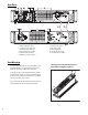
Input Configuration Switch (PLX 1802/2502/3102/3602 models only) Select the input configuration by sliding the switch to the position which corresponds with the desired input configuration. Input Configuration selector switch •Bridge- upper position •Stereo- middle position •Parallel- lower position Stereo Mode: Each channel remains independent, and each may be used for a different signal. Parallel Mode: This setting connects both inputs together. One input signal feeds both channels.
Inputs Each channel has a balanced XLR (female) and 1/4-inch TRS input. The XLR and TRS connectors for each channel are wired in parallel and can be used for “daisy chaining” an input signal to additional amplifiers. Input connectors and pinout chart (PLX1802 shown) The input impedance is 20k ohm balanced or 10k ohm unbalanced. Both XLR and TRS inputs are connected with standard cables and can be changed quickly. Pinouts are marked on the rear panel.
Outputs The PLX 1104 and PLX 1804 models are equipped with Speakon output connectors for each channel. PLX 1802, PLX 2502, PLX 3102, and PLX 3602 models are equipped with Speakon and binding post output connectors. PLX 1104 and PLX 1804 Output Connectors: Do not use less than 4 ohm impedance loads with PLX 1104 and PLX 1804 models. Wiring connections are shown on the back of the chassis. Carefully note the markings and maintain consistent loudspeaker polarity for optimum system performance.
LED Indicators The LED indicators can be used to monitor system operation and identify common problems. POWER (PWR): BLUE LED indicators on PLX 1104 and PLX 1804 models Normal indication: •AC switch ON: LED will illuminate. If no indication: •Check AC power cord and AC outlet. •Confirm that AC switch is in ON position. CLIP: RED Normal indication: •Illuminates whenever the amplifier is driven beyond full power. The resulting distortion corresponds to the brightness of the LED.
Gain Controls Turn the GAIN controls clockwise to increase gain and counter clockwise to decrease gain. Gain controls and LED cluster on PLX 1104 and PLX 1804 models The GAIN controls are marked in dB of attenuation. There are 21 detents for repeatable adjustments. The upper 14 steps are about 1 dB each, and settings should normally be made within this range.
Protection Systems Both amplifier platforms are fully protected against adverse conditions, but their behavior and user adjustments are different. PLX 1802/2502/3102/3602 models: •Clip Limiting may be switched on the rear panel to prevent severe overdrive. This protects speakers and somewhat reduces the load on the amplifier. •Internal current limits protect the output transistors against overloading.
Specifications PLX 1104, PLX 1804 PLX 1104 PLX 1804 20 - 20k Hz, 0.05% THD, 8 ohms/Ch. 1k Hz, 0.1% THD (EIA), 8 ohms/Ch. 20 - 20k Hz, 0.05% THD, 4 ohms/Ch. 1k Hz, 0.1% THD (EIA), 4 ohms/Ch. 310 325 500 550 550 600 800 900 DISTORTION, SMPTE-IM 0.02% 0.02% FREQUENCY RESPONSE 20 - 20k Hz, ±0.5 dB, all models SIGNAL to NOISE, unweighted, 20 - 20k Hz -108 dB -106 dB VOLTAGE GAIN 32.5 dB 34.9 dB INPUT SENSITIVITY, Vrms for rated power into 8 ohms 1.18 (+3.7 dBu) 1.20 (+3.
Specifications PLX 1802, PLX 2502, PLX 3102, PLX 3602 PLX 1802 PLX 2502 PLX 3102 PLX 3602 20 - 20k Hz, 0.05% THD, 8 ohms/Ch. 1k Hz, 0.1% THD (EIA), 8 ohms/Ch. 20 - 20k Hz, 0.05% THD, 4 ohms/Ch. 1k Hz, 0.1% THD (EIA), 4 ohms/Ch. 1k Hz, 0.1% THD (EIA), 2 ohms/Ch. Bridge Mono, 20 - 20k Hz, 0.1% THD, 8 ohms Bridge Mono, 1k Hz, 0.1% THD, 8 ohms Bridge Mono, 1k Hz, 1.
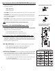
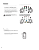
Appendix A: Speakon Wiring Reference Amplifier connection To loudspeaker Two-wire, single-channel connection Four-wire, two-channel connection NOTE! Ensure proper polarity when connecting bridge mode output! Bridge mode connection 14
How to Contact QSC Audio Products Cómo comunicarse con QSC Audio Products Comment prendre contact avec QSC Audio Products Kontaktinformationen für QSC Audio Products 联系 QSC Audio Products Mailing address: QSC Audio Products, Inc.