500 Series User Guide Revision 1.9 September, 2010 Disclaimer: The specifications in this document are subject to change without notice. All trademarks mentioned in this document are the property of their respective owners, and are used herein for informational purposes only. 2007-2010 Quantum Scientific Imaging Phone 888-QSI-4CCD • www.QSImaging.
Table of Contents 1. GETTING STAR TED Camera Selection 20 Status Indicators 21 What’s In the Box? 2 Imaging Options 22 Get to Know Your Camera 3 Other Options 22 Install Software and Drivers 4 Enable Pixel Masking 23 Confirm Installation and Camera Operation 4 Status and Notification 25 Launch MaxIm LE 4 Camera Status Indication 25 Connect the camera 5 Camera Error Indication 25 Take an image 7 Audible Beeper 27 View the image 8 Imaging Application Messages 27 2.
4. TAKING 5. GUIDING IMAGES Launch MaxIm LE 39 Autoguider support in MaxIm LE 65 Camera Control Window 40 Using an AutoGuider 66 Cool the CCD 42 Using a QSI 500 Series Camera as an Focusing with MaxIm LE 43 AutoGuider Take a single image 44 View the image in MaxIm LE 45 6.
Q S I 5 0 0 S E R I E S U S E R 1 Section G U I D E Getting Started Thank you for your purchase of a QSI 500 Series Camera. The QSI 500 Series family of thermoelectrically cooled CCD cameras is designed to produce scientific-grade images with wide dynamic range, excellent linearity and low noise. Your QSI 500 Series camera will provide years of service if properly treated and maintained.
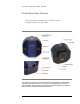
Q S I 5 0 0 S E R I E S U S E R G U I D E What’s In the Box? Your QSI 500 Series camera was shipped in a water-tight Pelican case with custom-cut foam to provide the ultimate in protection. Please take a few minutes to examine your camera to make sure that it has arrived in good condition, and that the case contains the items listed below. Note that additional items purchased at the time of order may be included as well.
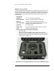
Q S I 5 0 0 S E R I E S U S E R G U I D E Get to Know Your Camera Take a few minutes to familiarize yourself with the external connections and features of your camera. The image above shows the major external features of a typical QSI 500 Series camera. The depth of the Camera Cover on your camera may differ depending on the internal options installed. See the “QSI 500 Series WSG User Guide Supplement” for additional details on WSG models with the Integrated Guider Port.
Q S I 5 0 0 S E R I E S U S E R G U I D E Install Software and Drivers The USB drivers and associated software included on the installation CD-ROM must be installed before connecting your QSI camera to your computer. Note: Do not connect your camera to your computer until instructed to do so during the camera installation process. Refer to the QSI 500 Series Camera Installation Guide for complete software and hardware installation instructions.
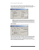
Q S I 5 0 0 S E R I E S U S E R G U I D E Connect the camera Select “Camera Control Window” from the View menu to open the Camera Control Window. MaxIm will open the Camera Control window and display the Setup tab. After MaxIm is installed it must be told which camera to use. Click the “Setup” button in the upper left corner under Main CCD Camera.
Q S I 5 0 0 S E R I E S U S E R G U I D E Select “QSI Universal” from the Camera Model list box. Click OK. That will take you back to the Camera Control Window. If you have a QSI camera with an internal color filter wheel you’ll also need to tell MaxIm about that by clicking “Setup” under “Filter Wheel” toward the upper right of the Setup tab. Select “QSI Universal” as the filter wheel model. Click OK.
Q S I 5 0 0 S E R I E S U S E R G U I D E Click the “Connect” button to establish communication between MaxIm and your QSI camera. If MaxIm fails to connect to the camera, double-check that power is supplied to the camera and that the USB cable is securely connected. Once MaxIm connects to the camera the Camera Control window will look like this: Note: This example assumes the camera does not have a color filter wheel.
Q S I 5 0 0 S E R I E S U S E R G U I D E View the image MaxIm will instruct the camera to acquire a bias frame and then automatically download and display the resulting image. Your screen should look something like this. Your display may vary somewhat from the screen shot above and the image displayed may be larger or smaller than that shown depending on your camera model.
Q S I 5 0 0 S E R I E S U S E R 2 Section G U I D E Camera Features and Operation Camera Attachment Options The camera can be attached to your telescope or lens in a variety of ways. The image above shows the industry standard T-Adapter with an attached 2" nosepiece. An optional 1.25" nosepiece is also available. The T-Adapter is compatible with a wide variety of standard accessories. A larger diameter 2.156” adapter is available for WSG models. An optional C-Adapter adapter is also available.
Q S I 5 0 0 S E R I E S U S E R G U I D E Using SLR Lenses The C-Adapter and T-adapter can be used to attach many standard SLR lens attached to your camera. The image at the right shows an Olympus OM series SLR lens attached to a QSI Model 520i camera. Optional SLR lens adapters are available to fit a variety of popular SLR camera lenses. See Section 6 in this Guide for a list of available adapters and compatibility requirements.
Q S I 5 0 0 S E R I E S U S E R G U I D E Electrical Connections The image at the left is a closeup of the bottom of the camera body. All electrical connections to the camera are made through the three connectors located on this connector panel. The panel is recessed into the camera body to protect the connectors when no cables are attached. DC Power Connector The camera is ordinarily powered by the included AC power adapter which plugs into the middle connector on the bottom of the camera.
Q S I 5 0 0 S E R I E S U S E R G U I D E Note: The camera power connecter uses a standard 2.1mm coaxial DC power connector with center positive. Inside diameter 2.1mm, outside diameter 5.5mm, length 10mm. Caution: Because of the wide range of potential power sources (especially with field operations that can also employ batteries, generators, DC inverters, etc.
Q S I 5 0 0 S E R I E S U S E R G U I D E Guider Control Port All QSI 500 Series cameras have a Guider Control Port that can be used in conjunction with MaxIm LE (or other CCD imaging software) to 'guide' your telescope mount for longduration astro-imaging. Ordinarily, the Port is only operational if the camera is being used as the 'Guider' camera, or if you’re using the QSI camera as your main imaging camera and have configured MaxIm to send guider correction signals through the ”Main Relays”.
Q S I 5 0 0 S E R I E S U S E R G U I D E Cooling the Camera Cooling the CCD is essential for successful astro-imaging. Cooling dramatically reduces the dark current and resulting thermal noise in an image and makes long exposures practical. See the discussion in the 'CCD Imaging Overview' Section on dark current and noise. QSI 500 Series cameras use a very efficient thermo-electric cooler (TEC) which relies on the 'Peltier Effect' to cool the CCD.
Q S I 5 0 0 S E R I E S U S E R G U I D E There are numerous ways of supplying recirculating water for the camera. One of the simpler and more common methods for astro-photography is to place a small submersible pump into a 5 gallon plastic pail full of cool water. The temperature of this amount of water will rise by only a few degrees after a full night of imaging. For additional details on the Liquid Heat Exchanger, see the Accessories section below.
Q S I 5 0 0 S E R I E S U S E R G U I D E When using forced-air cooling the body of the camera and the window of the CCD chamber can be up to 12ºC warmer than the surrounding ambient air temperature. By definition, the camera will be above the dew point (or frost point) and condensation will not form.
Q S I 5 0 0 S E R I E S U S E R G U I D E The following is an image of the same Camera Control window 5 minutes after clicking the Cooler On button. Notice that the CCD temperature is now being regulated at 0ºC and that the power level has settled down to a modest 40%. Note: Depending on the ambient temperature and Cooler setpoint, the time to reach the setpoint temperature can take as long as 15 minutes.
Q S I 5 0 0 S E R I E S U S E R G U I D E Internal Color Filter Wheel A five position filter wheel is available for some models of QSI 500 Series cameras. The filter wheel is designed to hold five standard 1.25" filters, and on some models, optional unmounted 31mm filters. The following image shows filter positions 1-4 occupied by red, green, blue and luminance filters respectively. Those are the standard filter positions if your camera was configured at the factory with LRGB filters.
Q S I 5 0 0 S E R I E S U S E R G U I D E Advanced Setup Options The QSI Configuration dialog box is used to view or change camera settings that are seldom modified. Bring up the Camera Control dialog box and click the Setup tab. The camera must be disconnected to proceed further. If necessary, click the Disconnect button. Click the Setup button in the upper left corner under “Main CCD Camera” to open the Setup QSI Universal dialog box for the Main camera.
Q S I 5 0 0 S E R I E S U S E R G U I D E Note: The very first time a QSI camera is connected to the computer it will set the relevant options shown above to default values based on the configuration of the specific camera. From that point forward, the settings are maintained in the Windows Registry. All subsequent changes are made to these Registry settings. This allows the computer to always know your last selections for each camera and restore them the next time you begin imaging.
Q S I 5 0 0 S E R I E S U S E R G U I D E If a camera has previously been assigned to another role, it will not appear in the list. For example, if a camera is currently assigned as the Main camera, it will not appear as an option in the Guider selection list box. Ethernet Interface Disabled on QSI 500 Series cameras Note: If only one camera is connected to the computer, the computer will always select that camera by default. You do not need to make the selection here.
Q S I 5 0 0 S E R I E S U S E R G U I D E Imaging Options Camera Gain Default setting is “High”. This setting can only be changed on cameras that support switchable gain. With supported cameras, gain can be set to “Low” in order to utilize the full dynamic range of the CCD when using on-chip binning. “High” gain is generally used for 1x1 binning. “Low” binning is recommended for binning settings other than 1x1. Shutter Priority Settings are “Mechanical” or “Electronic”.
Q S I 5 0 0 S E R I E S U S E R G U I D E Cooling Control For camera control applications that do not provide a way to enable cooling or control the set point temperature, cooling can be turned on by clicking the checkbox next to “Cooler On.” The desired temperature can then be set in the text box in degrees Celsius.
Q S I 5 0 0 S E R I E S U S E R G U I D E Advanced Dialog box showing the “Mask Pixels” table The current camera status is shown in the text field to the left of the OK and Cancel buttons. Click the OK button to save your changes or the Cancel button to abort them. This will return you to the Setup QSI Universal window. Click OK again and you'll be returned to the Setup tab in the Camera Control window.
Q S I 5 0 0 S E R I E S U S E R G U I D E Status and Notification QSI 500 Series camera utilizes a variety of methods to inform the operator of the camera's operation, status and other events. A built-in LED Status Indicator and audible Beeper provide notification at the camera. In the event of a serious internal error, the camera will also pass a descriptive error code back to the controlling application which then reports it to the user.
Q S I 5 0 0 S E R I E S U S E R G U I D E Camera Soft Error State Indication Flash Red: 1 Flash Yellow: 1 Flash Red: 1 Flash Yellow: 2 Flash Red: 1 Flash Yellow: 3 Flash Red: 1 Flash Yellow: 4 Flash Red: 1 Flash Yellow: 5 Flash Red: 1 Flash Yellow: 6 The camera is over-temperature. Camera has exceeded the 40°C maximum recommended operating temperature for the internal electronics and enclosure.
Q S I 5 0 0 S E R I E S U S E R G U I D E Camera Hard Error State Indication Flash Red: 2 Flash Yellow: N The number of yellow flashes of the Status Indicator specifies the nature of the camera Hard Error. This code indicates the technical nature of the problem. Note: Neither class of error indications can be disabled with the Advanced Dialog box. If you encounter any of these errors, make a record of the code flashed by the Status Indicator.
Q S I 5 0 0 S E R I E S U S E R 3 Section G U I D E CCD Imaging Overview This section is intended only as a brief overview of CCDs and CCD Imaging. If you are new to CCD imaging there are a number of excellent books that you can use to gain a deeper understanding of the issues and techniques.
Q S I 5 0 0 S E R I E S U S E R G U I D E prevent light from falling on the CCD surface while the image is being shifted out of the CCD. Interline Transfer CCDs Interline transfer CCDs work somewhat differently. In an interline transfer CCD, next to every column of pixels is a specialized storage column that is covered by a mask to prevent light from hitting the storage 'pixels' underneath. When an exposure is complete, the entire image is shifted in a single operation into this masked storage column.
Q S I 5 0 0 S E R I E S U S E R G U I D E draining off excess electrons before they exceed the capacity of the pixel. This can increase the dynamic rage of the CCD by as much as 300 times or more. This increase in dynamic range greatly reduces the difficulty of imaging bright objects. Anti-blooming CCDs make astrophotography more convenient, but with tradeoffs in quantum efficiency (QE) and linearity.
Q S I 5 0 0 S E R I E S U S E R G U I D E red, green and blue filters. The resulting images are then combined using computer image processing programs into a final color image. Single-shot color CCDs, like those found in almost all general use digital cameras, are made by placing red, green and blue filters over adjacent pixels in the CCD. The image processing program then has to separate the three different color images and recombine them into a single color image.
Q S I 5 0 0 S E R I E S U S E R G U I D E Reducing noise in CCD images CCD imagers have developed a standard set of calibration techniques to reduce or eliminate different types of noise from CCD images. Calibrating CCD images requires taking some special kinds of exposures that are then applied to the “light frames” taken of the night sky. The calibration frames are called Dark Frames, Flat Fields and Bias Frames. MaxIm LE and other CCD camera control software help gather these extra frames.
Q S I 5 0 0 S E R I E S U S E R G U I D E 6-minute Dark Frame Above is a 6-minute dark frame taken during the same imaging session with the above image of M78. Notice the brighter pixels scattered randomly around the image. Note: The pixel values in this image have been stretched significantly to show the variations in the dark frame. In reality this image is almost completely black with perhaps a few hundred “hot” pixels.
Q S I 5 0 0 S E R I E S U S E R G U I D E Original image Original image minus dark frame Look at the two images above. The top image is the original image as it came out of the camera. The bottom image has had the average of 5 dark frames subtracted from it. Note that the bright pixels have been virtually eliminated leaving a smooth black sky background.
Q S I 5 0 0 S E R I E S U S E R G U I D E The image above has been manipulated to highlight the effect of dust motes on a filter or CCD cover glass. Note the 3 darker circles. Because dust will tend to stay in one place over a night of imaging, the variation in pixel values caused by the dust can be easily eliminated by properly applying a Flat Field. A flat field is created by taking an image of an evenly illuminated subject. There are four common ways to create flat fields.
Q S I 5 0 0 S E R I E S U S E R G U I D E because flat fields tend to use fairly short exposures, you can often take a full series of flat fields and flat-darks in just a few minutes. The resulting master Flat Field is used to scale the pixel values in the light frame, eliminating the effects of pixel non-uniformity, optical vignetting and dust on the optical surfaces.
Q S I 5 0 0 S E R I E S U S E R G U I D E Stacking Images After calibrating each of your raw images with dark frames, flat fields and bias frames, combining or “stacking” multiple sub-exposures can be used to further reduce the noise in your images. Stacking multiple images with a pixel-by-pixel average or median combine tends to increase the signal to noise ratio (SNR) of the combined image.
Q S I 5 0 0 S E R I E S U S E R G U I D E of diminishing returns. Combining 18 frames will not yield a final image twice as good as combining 9 frames. Also note that in some cases, doing a “median combine” rather than an “average combine” may yield better results. A median combine is recommended if several of the individual frames have unique anomalies such as bright pixels caused by cosmic rays, satellites, airplanes, etc.
Q S I 5 0 0 S E R I E S U S E R 4 Section G U I D E Taking Images with your QSI 500 Series Camera Launch MaxIm LE Note: This section uses MaxIm LE as the camera control application. If you use a different camera control application, it will support similar operations. Launch MaxIm LE by double-clicking the MaxIm LE icon on your desktop or select “Programs > MaxIm LE > MaxIm LE” from the Windows Start menu.
Q S I 5 0 0 S E R I E S U S E R G U I D E Camera Control Window Select “Camera Control Window” from the View menu to open the Camera Control Window. MaxIm should open the window and display the Setup tab. If another tab is displayed, click the Setup tab. MaxIm may recognize your QSI camera and automatically show it as the default camera in the Main CCD Camera field.
Q S I 5 0 0 S E R I E S U S E R G U I D E If you don’t see “QSI Universal” listed in the Main CCD Camera field, click the “Setup” button in the upper left corner under Main CCD Camera. The window below will open. Select “QSI Universal” from the pop-up menu. Click OK. That will take you back to the Camera Control Window. Click the “Connect” button to establish communication between MaxIm and your QSI camera.
Q S I 5 0 0 S E R I E S U S E R G U I D E Cool the CCD To set the CCD cooling temperature you must first turn Cooling on by clicking the “Cooler On” button just to the left of the Connect button. After turning cooling on, the Camera Control window will look like this: The camera will immediately begin cooling the CCD to achieve the current setpoint temperature. To select a different setpoint temperature, click the “Cooler” button at the bottom left of the Main CCD Camera field.
Q S I 5 0 0 S E R I E S U S E R G U I D E Note: Please refer to the Cooling the Camera discussion in Section 2 Camera Features and Controls for in-depth information on cooling your 500 Series camera and the available cooling options. Focusing with MaxIm LE Achieving precise focus is critical for producing high quality astronomical photos. This seemingly simple task is surprisingly difficult when using the long focal lengths typical of astronomical telescopes.
Q S I 5 0 0 S E R I E S U S E R G U I D E Focus tab window should be set as shown above. You may need to adjust the exposure time in the “Seconds” field to the time necessary to see a few bright stars. Setting the exposure time as short as necessary to see a few bright stars allows you take more focus images in a shorter period of time, generally allowing you to achieve reasonably sharp focus fairly quickly. When you are satisfied with the focus, click “Stop”.
Q S I 5 0 0 S E R I E S U S E R G U I D E View the image in MaxIm LE When an exposure has completed, MaxIm will automatically download and display the image in a new window. After downloading the image, examine it to see if the target is properly framed and the exposure time is appropriate. The best astronomical images are achieved when the full dynamic range of the CCD is utilized. If you like the image, save it by selecting “Save” from the File menu.
Q S I 5 0 0 S E R I E S U S E R G U I D E minute image. Tracking errors, improper polar alignment, airplanes, satellites, and cosmic rays all conspire to make it difficult to be successful with very long exposures. Plus it’s a lot less frustrating to throw away one 5-minute exposure out of a total of 12 than a single 60minute exposure. MaxIm makes taking multiple sub-exposures easy. It’s even possible to set up an entire night of images and then go to sleep.
Q S I 5 0 0 S E R I E S U S E R G U I D E The Setup Sequence window allows you to set up 16 different groups of images to take during a single automated sequence. In the window above, we show 6 different steps in the sequence. MaxIm LE will take five 360 second light frames each with the red, green and then blue filters, ten 360 second light frames with the luminance filter, 12 360 second dark frames and 16 bias frames. The total duration of the sequence is shown along the bottom under “Duration.
Q S I 5 0 0 S E R I E S U S E R G U I D E The above numbers represent the minimum of each type of frame you should use. Taking more of each type of frame will further reduce the noise present in each calibration master image and improve your final results. Why you take different types of image calibration frames was discussed in some depth in the CCD Imaging Overview section. This section covers how to take the required calibration frames.
Q S I 5 0 0 S E R I E S U S E R G U I D E taken with the CCD at the same temperature as your light frames. If you’re taking LRGB or other filtered images, ideally you should take a set of flat fields through each filter. Setup your telescope and possibly your light box to take your preferred style of flats. Adjust the exposure so the average pixel is filled to approximately half its full well depth. With QSI 500 Series cameras you should strive for pixel values of roughly 30,000 ADUs.
Q S I 5 0 0 S E R I E S U S E R G U I D E Dark frame showing two cosmic ray hits in lower right hand quadrant Inspect your dark frames for cosmic ray strikes or other anomalous pixel groupings. The dark frame above shows two cosmic ray hits in the lower right quadrant of the image. Cosmic rays are energetic particles originating from somewhere in space.
Q S I 5 0 0 S E R I E S U S E R G U I D E Screenshot showing Pixel Math command ready to subtract a master dark frame. Select your light frame for Image A at the top and your master dark for Image B. Select “Subtract” for the operation. Click OK. You should see many of the bright pixels scattered around the light frame, disappear or get visibly darker. Do this with each of your light frames. After dark subtracting the individual light frames, the light frames can be combined into a master light frame.
Q S I 5 0 0 S E R I E S U S E R G U I D E 1. Produce a master dark flat following the steps above for creating a master dark frame. 2. Subtract the master dark flat from each of the flat fields. 3. Produce a master flat field by averaging the dark-subtracted flat field images. 4. Finally, divide the master flat field image into each of the dark-subtracted light frames. Save the resulting images with names that identify the frames as dark subtracted and scaled by a flat field.
Q S I 5 0 0 S E R I E S U S E R G U I D E Launch MaxIm LE. Choose “Set Calibration” from the Process menu. That will open the Set Calibration window. By default, MaxIm expects to calibrate images with bias frames, dark frames and flat fields. For this example we’re only going to show calibrating with bias frames and dark frames. Note: MaxIm also has a Calibration Wizard that steps you through the process of setting up your image calibration.
Q S I 5 0 0 S E R I E S U S E R G U I D E In the “Auto-Generation” panel near the bottom of the window, click the “…” button to the right of the text field and navigate to the folder that contains your images. In this example the images are contained in: My Documents\QSI\Astro Images\M78 QSI 504 060924\ Click the checkbox next to “Include Subfolders” if you’ve organized the images and calibration frames into subfolders within the main folder.
Q S I 5 0 0 S E R I E S U S E R G U I D E The upper panel lists the groups of calibration frames that MaxIm identified. The first calibration group should be selected. The lower “Group Properties” panel lists the files in the selected calibration group. Click on the group labeled “Dark1” in the upper panel to see the files in that group.
Q S I 5 0 0 S E R I E S U S E R G U I D E If MaxIm correctly identified all the calibration groups you created, you can click OK to close the Set Calibration window. Optionally you can click the “Replace w/Masters” button next to the Auto-Generate button. When Replace w/Masters is pressed, MaxIm will combine all the images in each calibration group and save the combined master image in the same directory as the individual frames. It will then modify the calibration groups to use each master frame.
Q S I 5 0 0 S E R I E S U S E R G U I D E MaxIm will apply each of the calibration groups you specified in the Set Calibration step to each of the open images. You can then choose to save the calibrated images or just leave them open in MaxIm. Tip: Be careful when saving the individual calibrated images not to overwrite the original image files. It is often useful to go back to the original uncalibrated images.
Q S I 5 0 0 S E R I E S U S E R G U I D E The dialog box above will open showing a list of all currently open files on the left. Select individual image files and then click the “>>” button to add them to the list of Selected Images or click the “Add All” button to add all the images. Click OK. This brings up the Combine Images dialog, which performs two related functions. It aligns and then combines the individual images.
Q S I 5 0 0 S E R I E S U S E R G U I D E The first image file is again the top window in MaxIm. Select a second alignment star near the opposite edge of the image. Repeat the process by clicking on the second star in each image. When you click on the star in the last image, MaxIm will make a bell sound indicating that the alignment process is complete. Make sure the Output field is set like you want: Sum, Average or Median.
Q S I 5 0 0 S E R I E S U S E R G U I D E If everything was done correctly the calibrated and combined image should show additional detail with less noise and greater contrast than the individual frames. Changing the range of displayed brightness levels in Screen Stretch window will show additional detail in different parts of the raw image file. Save the image with a name that allows you to identify this image as a combined master image. MaxIm provides additional tools for manipulating images.
Q S I 5 0 0 S E R I E S U S E R G U I D E Select the binning mode for a single exposure in MaxIm LE on the Settings tab of the Camera Control window. Note: MaxIm automatically adjusts the Width and Height fields to represent the size of the resulting image. In the example above 2x2 binning has been selected. This reduces the size of the resulting image of the QSI 504 from 768x512 to 384x256.
Q S I 5 0 0 S E R I E S U S E R G U I D E Note: When using binning other than 1x1, the pixels are combined inside the CCD before reading and converting the combined pixel charge to a numeric value. This results in lower overall noise than reading each pixel separately and combining them mathematically in your computer.
Q S I 5 0 0 S E R I E S U S E R G U I D E Using the internal Color Filter Wheel Some QSI 500 Series cameras include an internal 5-position color filter wheel. The color filter wheel is controlled automatically by MaxIm LE or other camera control software. If you ordered LRGB filters with your camera, the default order of the filters is as shown below: 1. Red 2. Green 3. Blue 4. Luminance 5.
Q S I 5 0 0 S E R I E S U S E R G U I D E Shutting down your camera QSI cameras can safely be turned off by removing the power cable at any time, however it is best to let the temperature of the CCD rise close to the air temperature before removing power. Click on the Setup Tab in the Camera Control window. Click the Cooler Off button to turn off the CCD cooler. The fans will continue to run dissipating heat from the thermoelectric coolers.
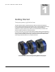
Q S I 5 0 0 S E R I E S U S E R 5 Section G U I D E Guiding The QSI 500 Series camera can be used as you main imaging camera or as an autoguider. MaxIm LE supports the following cameras as autoguiders. Other camera control software, such as MaxIm DL support additional autoguiders with a QSI camera.
Q S I 5 0 0 S E R I E S U S E R G U I D E Using an AutoGuider This section provides basic instructions on how to use your QSI 500 Series camera as your main imaging camera and set up a separate camera on a guide scope for guiding. For this example, we’re using a Meade DSI Pro as the autoguider. For complete instructions on guiding, including a step-by-step tutorial, please see the Online help in MaxIm LE. Setup your QSI 500 Series camera as described above.
Q S I 5 0 0 S E R I E S U S E R G U I D E Click the “Guide” tab to the left of the Setup tab. The Start button will be enabled if the autoguider camera was setup correctly. Click the black arrowhead to the right of “Options” below the Stop button and select “Guider Settings.
Q S I 5 0 0 S E R I E S U S E R G U I D E In the guider settings window, make sure that “Main Relays” is selected in the “Control Via” pop-up list under Autoguider Output. This instructs MaxIm to send the autoguider control signals through the Guider port on the QSI 500 Series camera. If your autoguider camera also has a guider port, you can select “Guider Relays” to send the signals through the autoguider camera. MaxIm supports additional methods of generating the correct control signals.
Q S I 5 0 0 S E R I E S U S E R G U I D E MaxIm LE automatically selects the brightest star as the guide star. You are now set up for guiding. Continue with instructions in the online help in MaxIm LE to calibrate your autoguider and begin tracking the selected guide star. For complete instructions on autoguiding in MaxIm LE please refer to the “Autoguiding” section of the online help in MaxIm.
Q S I 5 0 0 S E R I E S U S E R G U I D E Universal” under Camera Model and click OK to return to the Camera Control Window. Click Connect. Click the Guide tab and again click the black arrowhead to the right of “Options” below the Stop button and select “Guider Settings.” Select “Guider Relays” in the “Control Via” pop-up list under Autoguider Output. This instructs MaxIm to send the autoguider control signals through the Guider port on the QSI 500 Series camera now being used as the autoguider.
Q S I 5 0 0 S E R I E S U S E R 6 Section G U I D E Accessories T-mount adapter The T-mount adapter plate attaches to the front of the camera body. It comes standard on all QSI 500 Series cameras. The T-mount adapter is threaded with standard T-mount threads, 42mm diameter by 0.75mm pitch. 2” nosepiece The 2” nosepiece screws into the T-mount adapter plate. The 2” nosepiece allows the camera to be mounted in any 2” eyepiece adapter.
Q S I 5 0 0 S E R I E S U S E R G U I D E SLR lens adapter SLR lens adapters are available for the following lens mounts: Canon EF (EOS) Nikon F The SLR lens adapter provides the correct focal distance for specified lenses when threaded to the standard T-mount adapter on full-size “ws” model cameras. Standard extension tubes or T-mount extenders should be used to achieve the correct focal distance with slim or mid-size bodies. Mid-size bodies will require a 0.5” extension tube.
Q S I 5 0 0 S E R I E S U S E R 7 Section G U I D E Care & Maintenance Cleaning the exterior The QSI 500 Series cameras are machined from military grade 6061 aluminum with a very durable anodized finish that resists most scratches and fingerprints. Use a soft cloth to remove dirt or spots from the exterior surface of the camera. Installing or removing color filters To change filters or replace the color filter wheel the front cover of the camera must be removed.
Q S I 5 0 0 S E R I E S U S E R G U I D E Installing or removing 31mm color filters Some QSI 500 Series Color Filter Wheels are configured to hold unmounted 31mm filters. Filter wheels capable of holding 31mm unmounted filters have a screw hole between each filter position. Note the retaining screws in the image above between each filter position which hold the unmounted 31mm filters in place. Different retaining screw/washer combinations are used to hold different thickness filters.
Q S I 5 0 0 S E R I E S U S E R G U I D E Cleaning the color filters As with any precision optical surface, the optical coatings or glass of color filters can be permanently damaged by improper cleaning procedures. For best results follow the cleaning instructions that came with your filters. It is best to clean the filters infrequently and use the least intrusive of the methods below to remove any dust or fingerprints. 1. Blow any dust off the filter with clean, dry compressed air. 2.
Q S I 5 0 0 S E R I E S U S E R G U I D E If a single QSI camera is selected, its serial number will be shown in the “Select Camera” pop-up menu. Click Refresh to scan for connected QSI cameras. If multiple cameras are attached, select the camera you wish to update. The Model, Firmware, Serial No. and Mfg Date fields will be updated to reflect the currently selected camera. Click the “Browse” button to select the new firmware file.
Q S I 5 0 0 S E R I E S U S E R G U I D E Recharging the desiccant The environmental chamber enclosing the CCD is filled with UHP argon during manufacturing to increase cooling capability and prevent the formation of frost on the CCD cover glass. This ultra dry and clean noble gas will generally remain in the environmental chamber for about 3 years.
Q S I 5 0 0 S E R I E S U S E R G U I D E Note: Your camera can also be returned to QSI to have the environmental chamber purged and refilled with UHP argon gas and the desiccant recharged. Argon has better thermal insulating properties than air and provides the best results but the camera will work extremely well in most conditions with just air in the chamber and an active desiccant plug. Contact QSI Support for details.
Appendix A – 500 Series Specifications General Camera Specifications Feature QSI 500i Models QSI 500s Models QSI 500ws Models Electronic Shutter (Interline transfer CCDs only) 100µsec to 240 minutes 100µsec to 240 minutes 100µsec to 240 minutes Mechanical Shutter - 0.03 seconds to 240 minutes 0.03 seconds to 240 minutes Internal Color Filter Wheel No No Yes - 5 Position, 1.25" std filters Camera Body Configuration Slim Enclosure Medium Enclosure Full Enclosure Dimensions W4.45”x H4.
Model 504 CCD Specifications Feature Standard Optional Optional Model 532 CCD Options Kodak KAF-0402ME Kodak KAF-0402E Kodak KAF-0401LE CCD Architecture Full Frame Full Frame Full Frame Blue Enhanced Yes Yes No Microlens Yes No No No No Yes, 300x suppression Imager Size: (WxH) Anti-blooming 6.91mm x 4.6mm 6.91mm x 4.6mm 6.91mm x 4.
Model 532 CCD Specifications Feature Standard Optional Model 532 CCD Options Kodak KAF-3200ME Kodak KAF-3200E CCD Architecture Full Frame Full Frame Blue Enhanced Yes Yes Microlens Yes No No No Imager Size: (WxH) Anti-blooming 14.85mm x 10.26mm 14.85mm x 10.26mm Pixel Array (WxH): 2254x1510 total pixels, 2184x1472 active (visible) 2254x1510 total pixels, 2184x1472 active (visible) Pixel Size: 6.8µm x 6.8µm 6.8µm x 6.
Model 540 CCD Specifications Feature CCD Manufacturer & Model 540 Kodak KAI-04022 CCD Architecture 540c Kodak KAI-04022 (Color) Interline Transfer Microlens Yes Anti-blooming Color Filters Yes - 300x suppression Yes - Internal RGB on CCD; Bayer color filter mask No Imager Size: (WxH) 15.15mm x 15.15mm Pixel Array (WxH): 2112x2072 total pixels, 2048x2048 active (visible) Pixel Size: 7.4µm x 7.
Appendix B – Warranty QSI Warranty Policy The limited warranty set forth below is provided by Quantum Scientific Imaging, Inc. for QSI Scientific Cameras when purchased directly from QSI or an authorized QSI dealer within the dealer's authorized territory. This limited warranty also covers the following accessories if they were included with your original purchase: carrying case, AC power adapter, AC cable, and USB cable.
Shipping Costs The customer is responsible for all costs in shipping to QSI. QSI will pay shipping costs when returning a product to the customer. All replacement/repaired products are shipped via UPS Ground unless a rush is requested. The cost of such a shipping upgrade is to be paid by the customer prior to shipment.