Q70 – Base Station Radio Modem Quick Start Guide
Q70 – Quick Start Guide – v1.1 – December 2011 INTRODUCTION The Q70 Data Modem has been designed to reliably transmit and receive RS232 data and is the ideal modem for DATRAN base station. The modem is a direct replacement of the previous DATRAN base station modem, part number PD9300 (300bps) and PD9301 (1200bps). The Modem is supplied complete with a serial interface lead and a dedicated 12V DC plug pack to simplify the introduction.
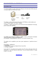
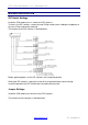
Q70 – Quick Start Guide – v1.1 – December 2011 MODEM CONFIGURATION DIP Switch Settings Inside the Q70 modem case is a bank of 8 DIP switches. To access the DIP switches, remove the two Phillips head screws holding the endplates to the case. Either end can be removed. The function of the DIP switches is defined below: Before applying power, set the DIP switches to the required position. Setting the DIP switches is generally a one off task required before commissioning.
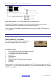
Q70 – Quick Start Guide – v1.1 – December 2011 Before applying power, set the PCB jumpers to the required position. Setting the PCB jumpers is generally a one off task required before commissioning. In normal operation the PCB jumpers do not need to be accessed. QTech supply the Q70 modems preconfigured to your existing settings. Please advise if this is required. MODEM CONNECTIONS Serial Connector - D9 Female The connector is labelled “Serial Connector” and connects the Modem to the base station PC.
Q70 – Quick Start Guide – v1.1 – December 2011 Radio Connector - RJ 45 The connector is labelled “Radio” and connects the Modem to the audio interface on the radio. Pin 1 is on the left hand side, nearest the fixing screw. The cable from this connector to the radio is provided with each Q70 modem Pin Number Function 1 2 Wire Transmit and receive audio data. 2 2 Wire Transmit and receive audio data. 3 Transmitter Key Power. 4 Transmitter key from Radio. 5 Ground. 6 Busy from Radio.