Operation & Service Manual 823111 2/01 15QNPD-D & 15QNPDF-D NUTPLATE DRILL Recoules Operation Zone industrielle - B.P.
Safety Recommendations For your safety and the safety of others, read and understand the safety recommendations and operating instructions before operating any drill motor. ! • Before the tool is connected to the air supply, the throttle should be checked for proper operation (i.e., throttle valve moves freely and returns to closed position). Always wear protective equipment: ! WARNING • Before removing a tool from service or changing drill bits, make sure the air line is shut off and drained of air.
Safety Recommendations Due to the number and variety of tooling applications, the user's methods engineering departments, ect., must consider any hazards that may be associated with each specific application of this product and provide adequate operator protection from Keep hands away from inadvertent contact with any moving clamping and feed components. The clamping and feed mechanisms.
Table of Contents Safety Recommendations 2&3 Major Tool Component Nomenclature 4 Introduction and General Information 5 Air Logic 6 Thru 8 Disassembly Section 9 Thru 26 Exploded Views and Parts List 27 Thru 38 Trouble Shooting Major Tool Component Nomenclature 4 39
Introduction and General Information The Q-Matic nut plate drill motor has been developed for drilling an countersinking the two holes required for attachment of nut plate fasteners. Utilizing an air/hydraulic system, and expanding collet grips the work with 240 lbs. holding force during the complete drilling and countersinking operation. The air powered motor develops 1HP and consumes 35 CFM at 90 psi, the recommended air line pressure. The tool developes 200 lbs.
! WARNING DISCONNECT AIR SUPPLY BEFORE SERVICING. THE CLAMPING AND FEED MECHANISMS ARE EXPOSED.TO AVOID INJURY, KEEP FINGERS AND HANDS AWAY FROM THESE AREAS WHEN HANDLING OR OPERATING TOOLS. Pressure Foot Attachment/Disassembly 1. Remove mandrel from lift finger by turning counterclockwise then remove the collet spring. 2. Remove the drills from spindles by holding spindles with an adjustable wrench on the flats of the spindles.
! WARNING DISCONNECT AIR SUPPLY BEFORE SERVICING. THE CLAMPING AND FEED MECHANISMS ARE EXPOSED.TO AVOID INJURY, KEEP FINGERS AND HANDS AWAY FROM THESE AREAS WHEN HANDLING OR OPERATING TOOLS. Pressure Foot Attachment/Disassembly — continued 3. Remove pressure foot by loosening clamp screw, then unscrew pressure foot attachment from collet closing piston rod. 4. Remove socket head cap screw 622060 from collet closing piston rod with hex wrench.
! WARNING DISCONNECT AIR SUPPLY BEFORE SERVICING. THE CLAMPING AND FEED MECHANISMS ARE EXPOSED.TO AVOID INJURY, KEEP FINGERS AND HANDS AWAY FROM THESE AREAS WHEN HANDLING OR OPERATING TOOLS. Pressure Foot Attachment/Disassembly — continued 5. Retract collet lift finger by applying pressure on the lift finger toward the tool. Remove lift finger from collet closing piston rod. Spindle and Backhead Disassembly 1. Remove four socket head cap screws 863408 from backhead.
! WARNING DISCONNECT AIR SUPPLY BEFORE SERVICING. THE CLAMPING AND FEED MECHANISMS ARE EXPOSED.TO AVOID INJURY, KEEP FINGERS AND HANDS AWAY FROM THESE AREAS WHEN HANDLING OR OPERATING TOOLS. Spindle and Backhead Disassembly — continued 2. Remove backhead and spindle assemblies from motor housing. NOTE: Four idler gears are held in position by idler gear shafts in the backhead, and are retained by front bearing plate 622090. Front bearing plate remains in place in motor housing bore. 3.
! WARNING DISCONNECT AIR SUPPLY BEFORE SERVICING. THE CLAMPING AND FEED MECHANISMS ARE EXPOSED.TO AVOID INJURY, KEEP FINGERS AND HANDS AWAY FROM THESE AREAS WHEN HANDLING OR OPERATING TOOLS. Spindle and Backhead Disassembly — continued 4. The spindle adjustment screw is removed by screwing the spindle clockwise through the backhead assembly 622091. 5. To remove spindle from spindle adjusting screw, remove retaining ring 623685 and insert end of spindle adjusting screw in vise.
! WARNING DISCONNECT AIR SUPPLY BEFORE SERVICING. THE CLAMPING AND FEED MECHANISMS ARE EXPOSED.TO AVOID INJURY, KEEP FINGERS AND HANDS AWAY FROM THESE AREAS WHEN HANDLING OR OPERATING TOOLS. Spindle and Backhead Disassembly — continued 6. Double row ball bearings 863582 are removed from spindle shaft by removing lock nut 623767 and driving shaft through bearings. To remove spindle gear 622097, remove retaining ring 833774 and slide spindle gear off shaft. Gear is held in place with key 622057.
! WARNING DISCONNECT AIR SUPPLY BEFORE SERVICING. THE CLAMPING AND FEED MECHANISMS ARE EXPOSED.TO AVOID INJURY, KEEP FINGERS AND HANDS AWAY FROM THESE AREAS WHEN HANDLING OR OPERATING TOOLS. Spindle Support Plate and Spindle Cover Disassembly — continued 2. Remove two button head screws 622059 from spindle support wedge 622082. 3. Lift out support plate and spindle cover from motor housing. NOTE: The sintered bronze muffler should be periodically removed and washed in solvent.
! WARNING DISCONNECT AIR SUPPLY BEFORE SERVICING. THE CLAMPING AND FEED MECHANISMS ARE EXPOSED.TO AVOID INJURY, KEEP FINGERS AND HANDS AWAY FROM THESE AREAS WHEN HANDLING OR OPERATING TOOLS. Air Motor Assembly Removal 1. Remove the gear plate 622101 and gear plate spacer 624354 (6,000 & 20,000 RPM tools only) from rear of motor housing. 2. Tap motor housing gently on table top to drop motor assembly out of housing.
! WARNING DISCONNECT AIR SUPPLY BEFORE SERVICING. THE CLAMPING AND FEED MECHANISMS ARE EXPOSED.TO AVOID INJURY, KEEP FINGERS AND HANDS AWAY FROM THESE AREAS WHEN HANDLING OR OPERATING TOOLS. Air Motor Assembly Removal — continued 3. Rear bearing support is removed by tapping the motor housing on cushioned bench top. The rear bearing support can also be removed using special internal grip pliers as shown in photo.
! WARNING DISCONNECT AIR SUPPLY BEFORE SERVICING. THE CLAMPING AND FEED MECHANISMS ARE EXPOSED.TO AVOID INJURY, KEEP FINGERS AND HANDS AWAY FROM THESE AREAS WHEN HANDLING OR OPERATING TOOLS. Air Motor Assembly Disassembly 1. Lift front bearing plate 622090 from alignment pin 812164. 2. Unscrew button head screw 615641 from rotor to remove rear bearing plate 864232. Remove rotor 622089 from cylinder 864236. Use small flat blade screwdriver to pry up bearing cap 864335. Four rotor blades will fall out.
! WARNING DISCONNECT AIR SUPPLY BEFORE SERVICING. THE CLAMPING AND FEED MECHANISMS ARE EXPOSED.TO AVOID INJURY, KEEP FINGERS AND HANDS AWAY FROM THESE AREAS WHEN HANDLING OR OPERATING TOOLS. Air Motor Assembly Disassembly — continued 3. Air motor assembly components. Feed and Clamp Cylinder Piston Disassembly 1.Using assembly tool 623334 for removing and installing front enclosure 624290 and two 1032 screws, remove retaining ring 622061 with pliers and lift out front enclosure bulkhead.
! WARNING DISCONNECT AIR SUPPLY BEFORE SERVICING. THE CLAMPING AND FEED MECHANISMS ARE EXPOSED.TO AVOID INJURY, KEEP FINGERS AND HANDS AWAY FROM THESE AREAS WHEN HANDLING OR OPERATING TOOLS. Feed and Clamp Cylinder Piston Disassembly — continued 2. Remove clamp feed shaft 622072 and piston 622070. 3. Remove retainer ring 622065. Using assembly tool 623334 and two 8-32 screws remove pressure head 624289.
! WARNING DISCONNECT AIR SUPPLY BEFORE SERVICING. THE CLAMPING AND FEED MECHANISMS ARE EXPOSED.TO AVOID INJURY, KEEP FINGERS AND HANDS AWAY FROM THESE AREAS WHEN HANDLING OR OPERATING TOOLS. Main Air Valve Assembly Removal 1. Set handle in vertical position and remove inlet bushing 622080, then lift out main air valve spring 622141. 2. Insert 8-32 screw into pilot spool 622007 and lift out pilot sleeve spacer 622081. Remove spool and pilot sleeve. Main air valve assembly components are shown on right.
! WARNING DISCONNECT AIR SUPPLY BEFORE SERVICING. THE CLAMPING AND FEED MECHANISMS ARE EXPOSED.TO AVOID INJURY, KEEP FINGERS AND HANDS AWAY FROM THESE AREAS WHEN HANDLING OR OPERATING TOOLS. Fluid Reservoir Assembly Removal 1. Remove hydraulic fill fitting 621762 from front of reservoir. 2. Insert small dowel against reservoir gage 622084 and push fluid reservoir gage through front of opening.
! WARNING DISCONNECT AIR SUPPLY BEFORE SERVICING. THE CLAMPING AND FEED MECHANISMS ARE EXPOSED.TO AVOID INJURY, KEEP FINGERS AND HANDS AWAY FROM THESE AREAS WHEN HANDLING OR OPERATING TOOLS. Fluid Reservoir Assembly Removal — continued 3. Push gage tube guide with dowel through front opening and remove from rear of housing. NOTE: Always replace with new O-rings. Trigger Assembly Removal 1. Remove set screw 622054 from trigger 622073 and pull trigger spool out of trigger spool 623691.
! WARNING DISCONNECT AIR SUPPLY BEFORE SERVICING. THE CLAMPING AND FEED MECHANISMS ARE EXPOSED.TO AVOID INJURY, KEEP FINGERS AND HANDS AWAY FROM THESE AREAS WHEN HANDLING OR OPERATING TOOLS. Trigger Assembly Removal — continued 2. Remove snap ring 864271 and pull trigger sleeve and trigger spool 623691 out of base. 3. Remover trigger return spring 622088 from bottom of trigger bore. Trigger assembly components.
! WARNING DISCONNECT AIR SUPPLY BEFORE SERVICING. THE CLAMPING AND FEED MECHANISMS ARE EXPOSED.TO AVOID INJURY, KEEP FINGERS AND HANDS AWAY FROM THESE AREAS WHEN HANDLING OR OPERATING TOOLS. Mounting Air Booster Pump 1. To install optional air booster pump, remove the comer plate 621439 by unscrewing three button head screws 622053. 2. Mount optional air booster pump assembly 621482 with three socket head cap screws and O-rings supplied with air booster pump kit.
! WARNING DISCONNECT AIR SUPPLY BEFORE SERVICING. THE CLAMPING AND FEED MECHANISMS ARE EXPOSED.TO AVOID INJURY, KEEP FINGERS AND HANDS AWAY FROM THESE AREAS WHEN HANDLING OR OPERATING TOOLS. Mounting Air Booster Pump — continued 3. NOTE: The booster pump is recommended for use only in the 600 rpm model tool. Feed Control Valve Removal 1. Using hex wrench, unscrew feed control needle valve part 622026. Remove from housing and replace O-ring 844301 to insure positive seal.
CLAMPING ASSEMBLY 624289-5 622065-1 622143-6 622065-1 622071-9 TO MOTOR 844310-3 864737-2 622086-7 622061-0 622062-8 614902-5 624290-3 844265-9 SPECIFIED BY CUSTOMER 622143-6 622070-1 622143-6 843518-2 622881-1 623811-7 614902-5 622060-2 622127-9 843518-2 622881-1 844265-9 622072-7 622065-1 622143-6 SPECIFIED BY CUSTOMER 625873-5 616514-6 .1875 I.D. 616302-6 .2500 I.D.
CLAMPING ASSEMBLY PARTS LIST MODEL NO. 203210-0 614902-5 616302-6 616514-6 622060-2 622061-0 622062-8 622065-1 622070-1 622071-9 622072-7 622086-7 622127-9 622143-6 622881-1 623811-7 624289-5 624290-3 625873-5 843518-2 844265-9 844310-3 864737-2 28 NAME OF PART Foot Guard Piston Retainer Ring Pressure Foot Bushing .2500 I.D. Pressure Foot Bushing .1875 I.D.
HANDLE ASSEMBLY 622085-9 622084-2 844304-6 ADD FLUID 844303-8 621762-4 844304-6 812962-9 622063-6 203246-4 622124-6 - Regular 622669-0 - Large 622059-4 Regular Model Only 624241-6 622082-6 Regular Model Only 622087-5 622064-4 622055-2 616302-6 844301-2 622026-3 843434-2 621439-9 623691-3 622073-5 622053-7 844301-2 622054-5 864271-2 622064-4 847710-1 Specified by Customer Regular Model Only 622088-3 203762-0 844306-1 622067-7 - Regular Specified by Customer - Large 844301-2 621385
HANDLE ASSEMBLY PARTS LIST MODEL NO.
MOTOR ASSEMBLY TO CLAMPING ASSEMBLY 847095-7 615641-8 864234-0 812164-2 TO GEAR TRAIN 622089-1 843913-5 864335-5 600 & 6000 864232-4 20,000 864236-5 622090-9 847511-3 622758-1 31
MOTOR ASSEMBLY PARTS LIST MODEL NO. 615641-8 622089-1 622090-9 622758-1 812164-2 843913-5 847095-7 847511-3 864232-4 864234-0 864236-5 864335-5 32 NAME OF PART Rear Bearing Retainer Screw Rotor Front Bearing Plate Rear Bearing Plate 20,000 RPM (Left Hand Rotation) Cylinder Roll Pin Rotor Collar Rear Rotor Ball Bearing Front Rotor Ball Bearing Rear Bearing Plate 600 & 6,000 RPM (Right Hand Rotation) Rotor Blade Cylinder Motor Bearing Cap QTY.
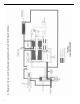
623766-3 623765-5* 863582-3 623767-1 622093-2 863582-3 623685-5 833774-3 622097-4 600 RPM GEAR TRAIN 622057-8 622097-4 623767-1 622057-8 833774-3 623685-5 863582-3 623766-3 844774-0 622102-2 844774-0 622103-0 842654-6 622105-5 613126-2 622106-3 842654-6 615553-5 622103-0 622093-2 619816-2 203245-6 863582-3 623765-5* 622100-6 * OPTIONAL SHIMS 864730-7- .001 Opt. 864731-5- .002 Opt. 864732-3- .005 Opt. 623765-5- .006 Std.
600 RPM GEAR TRAIN PARTS LIST MODEL NO.
623766-3 623765-5* 863582-3 623767-1 622093-2 863582-3 623685-5 833774-3 622097-4 6,000 RPM GEAR TRAIN 622057-8 622097-4 623767-1 622057-8 833774-3 623685-5 863582-3 623766-3 622093-2 619816-2 203245-6 863582-3 623765-5* 622100-6 844774-0 * OPTIONAL SHIMS 864730-7- .001 Opt. 864731-5- .002 Opt. 864732-3- .005 Opt. 623765-5- .006 Std.
6,000 RPM GEAR TRAIN PARTS LIST MODEL NO.
20,000 RPM GEAR TRAIN 623765-5* 863582-3 623767-1 622093-2 863582-3 623685-5 833774-3 622097-4 623766-3 622057-8 622097-4 833774-3 623685-5 863582-3 623766-3 619816-2 203245-6 863582-3 623765-5* 622142-8 844799-7 622100-6 844774-0 624354-7 622093-2 623767-1 622057-8 * OPTIONAL SHIMS 864730-7- .001 Opt. 864731-5- .002 Opt. 864732-3- .005 Opt. 623765-5- .006 Std.
20,000 RPM GEAR TRAIN PARTS LIST MODEL NO.
TROUBLESHOOTING GUIDE FOR 15 NUT PLATE DRILL MOTOR SYMPTOM REASON SOLUTION Air motor and/or clamp and feed functions do not start when trigger is depressed. Trigger or pilot valves clogged with foreign matter. Disconnect air line then remove trigger and pilot valves and inspect for debris. Inspect "O"-rings and replace if necessary. Air motor does not run when trigger is depressed, but feed and clamp functions work properly. Gears damaged or jammed with debris.