Upstream Quad Receiver 060558-001 Rev B Equipment Manual
Equipment Manual for Upstream Quad Receiver
Upstream Quad Receiver C-COR.net Document Number: 060558-001, Revision B Copyright © 2002 C-COR.net Corp. All rights reserved. Trademarks C-COR, C-COR Electronics, naviCOR, FlexNet, I-Flex, DV6000, SMART-NETT, Liteamp, and MobileFORCE are registered trademarks and lumaCOR, Optiworx, COR-Convergence, and COR-ISMS are trademarks of C-COR.net Corp. All other brand and product names are trademarks or registered trademarks of their respective companies.
Contacting C-COR.net Technical Support Contact Information You can contact C-COR.net by phone, e-mail, Internet, fax, or mail. When contacting C-COR.
Mail Send your letter including the information listed in Contact Information: Attn: Applications Engineering and Training Department C-COR.net Corp. 60 Decibel Road State College, PA 16801-7580 USA Providing Feedback on This Publication C-COR.net welcomes your suggestions and assistance in identifying any errors, inaccuracies, or misleading information. Please contact our Technical Publications Department with an e-mail referencing the document number and page number(s) to which the feedback applies.
About This Manual This manual contains the instructions needed to install the Upstream Quad Receiver used in the hybrid fiber/coax (HFC) access platform. Depending on the system design, the HFC access platform (also referred to as “the system”) can deliver various video, telephony, data, and special services over a network consisting of fiber optic and coaxial cables deployed in the local subscriber loop. Note: The HFC access platform components and capabilities will become available in various releases.
Admonishments Important safety admonishments are used throughout this manual to warn of possible hazards to persons or equipment. An admonishment identifies a possible hazard and then explains what may happen if the hazard is not avoided. The admonishments — in the form of Dangers, Warnings, and Cautions — must be followed at all times. These warnings are listed in descending order of severity of injury or damage and likelihood of occurrence.
Certification Safety UL1950, 2nd Edition/CSA C22.2 No. 950-M89, 11/4/97 EN60950: 1992 Incl. Amendments Nos. 1 and 2 EMC FCC: Part 15, Subpart B, 5/17/1994 Immunity: European Union EN50081-1 and EN50082-1 Warning: This equipment generates, uses, and can radiate radio frequency energy and if not installed and used in accordance with the instruction manual, may cause interference to radio communications.
List of Acronyms and Abbreviations The acronyms and abbreviations used in this manual are detailed in the following list: AC Alternating Current ACO Alarm Cut Off AM Amplitude Modulation ARMU Alarm Relay Module Unit ASCII American Standard Code for Information Interchange ATM Asynchronous Transfer Mode BRCU Basic Rate Channel Unit (ISDN) CXSU Coax Slave Unit CATV Cable Television CEV Controlled Environment Vault CXCM Coax Common Module (ISU - 12 lines) COAX Co-axial CPE Customer Pre
List of Acronyms and Abbreviations (Cont.
TABLE OF CONTENTS Content Page FRONT MATTER Contacting C-COR.NET Technical Support.............................................................................................................v Providing Feedback on This Publication ................................................................................................................ vi About This Manual ................................................................................................................................................
SECTION 1 INTRODUCTION Content Page 1. GENERAL .......................................................................................................................................... 1-1 2. SYSTEM OVERVIEW ...................................................................................................................... 1-1 1. General 1.01 This section provides an overview of how the Upstream Quad Receiver is used in the hybrid fiber/coax (HFC) access platform.
PN 060558-001 Revision B, January 2002 2.02 Each HFC access platform consists of many components, all of which are designed to function seamlessly together in an integrated system. The exact mix of components and equipment in a given system is dependent on the basic architecture of the system and the services it must provide. A diagram of a typical video and telephony HFC system is shown in Figure 1-1.
NMCS PUBLIC SWITCHED NETWORK LOCAL ORIGINATION OFF-THE-AIR MICROWAVE TRUNKED SATTELITE FEED MICRO MGR DV6000 XMTR VIDEO INFORMATION PROVIDER LDS, COT, OR DCS OSWORX ELEMENT MANAGER 750 MHZ XMTR X.
Page 1-4 © 2002, C-COR.
SECTION 2 DESCRIPTION Content Page 1. INTRODUCTION .............................................................................................................................. 2-1 2. OVERVIEW ....................................................................................................................................... 2-1 3. PHYSICAL DESCRIPTION ............................................................................................................. 2-1 A.
PN 060558-001 Revision B, January 2002 RECEIVER FRONT VIEW 12 V CPU GND RF MON CH 1 RF MON CH 2 RF MON CH 3 IPD LVL IPD SD RF MON CH 4 IPD LVL IPD IPD LVL SD IPD SD IPD LVL IPD SD RECEIVER REAR VIEW CH 4 OPT IN CH 2 CH 3 RF OUT OPT IN RF OUT OPT IN CH 1 RF OUT OPT IN RF OUT ADDRESS NMCS ALARM MAJOR MINOR -48 VDC 120/240 VAC FUSE 5120-C Figure 2-1 Upstream Quad Receiver 3.
PN 060558-001 Revision B, January 2002 Table 2-1. Front Panel Controls, Indicators and Connectors FEATURE DESCRIPTION IPD/SD (red LED) When lit it indicates that the particular channel is not being used if optical power is out of range, internal jumpers are provided to disable this feature. 12 V (green LED) When lit it indicates the 12 VDC power supply is operating normally. CPU (green LED) When lit it indicates the CPU in the receiver is operating normally.
PN 060558-001 Revision B, January 2002 CHASSIS GROUND RF OUTPUT - CH 4 CH 4 OPT IN CH 3 RF OUT OPTICAL INPUT - CH 4 OPT IN CH 1 CH 2 RF OUT OPT IN OPTICAL INPUT - CH 3 RF OUTUT - CH 1 RF OUTPUT - CH 2 RF OUTPUT - CH 3 OPT IN RF OUT OPTICAL INPUT CH 2 RF OUT OPTICAL INPUT CH 1 5122-C Figure 2-3 RF and Optical Connections ADDRESS SWITCH (0-9, A-F) NETWORK MANAGEMENT INTERFACE CONNECTIONS NMCS ADDRESS ALARM MAJOR FUSE MINOR ALARM CONNECTIONS 120/240 VAC -48 V FUSE -48 VDC OFFIC
PN 060558-001 Revision B, January 2002 Table 2-2 Rear Panel Controls and Connections FEATURE DESCRIPTION GROUND Spring-loaded chassis ground connection, connects to office ground conductor. OPT IN (CH 1 - CH 4) Optical input connection. One connector provided for each channel. RF OUT (CH 1 - CH 4) RF output connection. One connector provided for each channel. ADDRESS 16-position (hex) rotary switch used to set a unique identifying address to the receiver.
PN 060558-001 Revision B, January 2002 4. Specifications 4.01 Physical and performance specifications are shown in Table 2-3. Table 2-3 Specifications CHARACTERISTIC SPECIFICATION Dimensions Height 1.75 inches (4.45 cm) Width 19 inches (48.26 cm) Depth 11 inches (27.94 cm) Weight (approx.) 13 lbs. (5.9 kg) Mounting 19-inch equipment rack (EIA/WECO spacing) Power Requirements Input –48 VDC, 120 VAC, or 240 VAC (configured at factory). –48 VDC supports “A” and “B” battery plant.
SECTION 3 INSTALLATION Content Page 1. GENERAL .......................................................................................................................................... 3-1 2. USING A TOP DOCUMENT............................................................................................................ 3-2 3. ADMONISHMENTS ......................................................................................................................... 3-3 INSTALLATION TASK INDEX LIST ............
PN 060558-001 Revision B, January 2002 • Connect receiver chassis to office ground • Connecting cables to the optical input and RF output • Connecting major and minor alarms and NMCS interface • Connecting receiver to office power source • Performing initial turn-up and testing 2. Using a TOP Document 2.01 The procedures in this section are written in the Task Oriented Practice (TOP) format. TOP procedures are step-by-step instructions for completing the indicated task.
PN 060558-001 Revision B, January 2002 3. Admonishments 3.01 Various admonishments are used in the TOP procedures to warn of possible hazards to personnel or equipment. In general, an admonishment identifies a possible hazard and then explains what may happen if the hazard is not avoided. Admonishments are always printed in bold type to catch the attention of the reader.
PN 060558-001 Revision B, January 2002 ALPHABETICAL TASK LIST ASSIGN RECEIVER ADDRESS.....................................................................................................DLP-515 CHECK/ADJUST RF OUTPUT POWER LEVEL..........................................................................DLP-513 CHECK OPTICAL INPUT POWER LEVEL..................................................................................
PN 060558-001 Revision B, January 2002 IXL-001 Page 1 of 1 INSTALLATION TASK INDEX LIST Find Your Job in the List Below Then Go To INSTALL UPSTREAM QUAD RECEIVER .................................................................................. NTP-002 Inspect Installation Site ....................................................................................................................DLP-500 Unpack Equipment And Inspect For Damage .................................................................
PN 060558-001 Revision B, January 2002 Page 3-6 © 2002, C-COR.
PN 060558-001 Revision B, January 2002 NTP-002 Page 1 of 1 INSTALL THE UPSTREAM QUAD RECEIVER Summary: This procedure describes how to install the Upstream Quad Receiver in a serving office or end office receiver bay. Do Items Below in the Order Listed 1. For Details Go To Inspect the installation site to become familiar with the equipment location within the office. DLP-500 2. Unpack each receiver and inspect it for damage. DLP-501 3.
PN 060558-001 Revision B, January 2002 NTP-003 Page 1 of 2 INITIAL TURN-UP AND TEST Summary: This procedure describes how to perform the initial turn-up and testing of the receiver. Note: Turn-up and testing of the receiver is limited to applying power, verifying the operation of indicators, checking and adjusting initial receiver input and output levels. Do Items Below in the Order Listed For Details Go To 1. Apply office power to the receiver.
PN 060558-001 Revision B, January 2002 NTP-003 Page 2 of 2 Do Items Below in the Order Listed 6. 7. Verify that the receiver is capable of communicating with the MICRO Manager Software. For Details Go To DLP-514 Update office records as required by local practice. Stop! You have completed this section. Page 3-9 © 2002, C-COR.
PN 060558-001 Revision B, January 2002 Page 3-10 © 2002, C-COR.
PN 060558-001 Revision B, January 2002 DLP-500 Page 1 of 1 INSPECT INSTALLATION SITE Summary: This procedure is a review of the system and site plans to ensure that you are familiar with the system, the office where it will be installed, the equipment with which it interfaces, and the bay(s) in which it will be installed. 1. Obtain and familiarize yourself with the site plans. 2. Ensure the equipment racks have been installed. 3. Ensure the required ac power wiring is in place. 4.
PN 060558-001 Revision B, January 2002 DLP-501 Page 1 of 1 UNPACK EQUIPMENT AND INSPECT FOR DAMAGE Summary: This procedure is used to inspect and open the shipping boxes, to verify that all parts have been received, and to verify that no shipping damage has occurred. 1. Obtain the following tools and equipment that are required for unpacking the equipment: • ESD Wrist band • ESD anti-static mat • Box cutter Caution: Electronic equipment can be damaged by static electrical discharge.
PN 060558-001 Revision B, January 2002 DLP-502 Page 1 of 4 MOUNT RECEIVER IN RACK Summary: This procedure describes how to mount the receiver into the equipment rack. For installation in 23-inch equipment racks, an extender bracket must be added at each side of the front panel. Caution: To prevent electrical shock, never install electrical equipment in a wet location or during a lightning storm. Note: If the receiver is being installed in a 19-inch rack, start this procedure at step 3.
PN 060558-001 Revision B, January 2002 DLP-502 Page 2 of 4 RACK EXTENDER BRACKET ;; 8249-A FRONT PANEL SCREWS Figure 502-1 Installing 23-Inch Rack Extender Brackets Page 3-14 © 2002, C-COR.
PN 060558-001 Revision B, January 2002 DLP-502 Page 3 of 4 MAXIMUM CONFIGURATION CONFIGURATION FOR MAXIMUM COOLING FUSE & ALARM PANEL FUSE & ALARM PANEL COUPLER SPACE COUPLER SPACE RECEIVER RECEIVER RECEIVER RECEIVER RECEIVER RECEIVER RECEIVER RECEIVER RECEIVER RECEIVER RECEIVER RECEIVER RECEIVER RECEIVER RECEIVER RECEIVER RECEIVER RECEIVER RECEIVER RECEIVER RECEIVER RECEIVER RECEIVER RECEIVER RECEIVER RECEIVER SPACE SPACE 5140-A Figure 502-2 Receiver Spacing and Ventilation Pa
PN 060558-001 Revision B, January 2002 DLP-502 Page 4 of 4 23-INCH RACK CONFIGURATION 19-INCH RACK CONFIGURATION EQUIPMENT RACK FRONT PANEL EXTENDER BRACKET SCREW SCREW 4893-A Figure 502-3 Securing Receiver to Rack Page 3-16 © 2002, C-COR.
PN 060558-001 Revision B, January 2002 DLP-503 Page 1 of 2 CONNECT RECEIVER TO OFFICE GROUND Summary: This procedure establishes a ground connection using 16 AWG bus wire, between the receiver chassis and the office ground connection. This connection must be made in accordance with all local and national electrical codes. 1. Obtain the following: • ESD Wrist strap • Ground braid 2. Place the ESD wrist-band on your wrist and snap the ground wire to the wrist-band.
PN 060558-001 Revision B, January 2002 DLP-503 Page 2 of 2 TO OFFICE GROUND CONDUCTOR 16 AWG BUS WIRE MINIMUM GROUND CONNECTION CH 4 OPT IN CH 3 RF OUT OPT IN CH 1 CH 2 RF OUT OPT IN RF OUT OPT IN RF OUT ADDRESS 5126-B Figure 503-1 Connecting Receiver to Office Ground Page 3-18 © 2002, C-COR.
PN 060558-001 Revision B, January 2002 DLP-504 Page 1 of 2 CONNECT ALARMS Summary: This procedure connects the MAJOR, and MINOR alarm contacts on the receiver to the corresponding alarm connections on the fuse and alarm panel. Note: If the fuse and alarm panel has not yet been installed, the alarms can only be wired at the receiver. It will not be possible to perform initial turn-up and test procedures.
PN 060558-001 Revision B, January 2002 DLP-504 Page 2 of 2 RECEIVER REAR PANEL 120/240 VAC ALARM MAJOR MINOR FUSE AC POWER CORD CONNECTOR MINOR (COM) MINOR (N.O.) MAJOR (COM) TO FUSE AND ALARM PANEL MAJOR (N.O.) 5127-B Figure 504-1 Alarm Terminations on Rear Panel of the Receiver Page 3-20 © 2002, C-COR.
PN 060558-001 Revision B, January 2002 DLP-505 Page 1 of 2 CONNECT RECEIVER TO NMCS Summary: This procedure describes how to connect the network control interface on the receiver to the NMCS. Two RJ11 connectors are provided on the back of the receiver for this purpose. A daisy-chain cabling scheme is used. 1. 2.
PN 060558-001 Revision B, January 2002 DLP-505 Page 2 of 2 TO NMCS RECEIVER REAR PANEL CH 1 RECEIVER #1 RF OUT ADDRESS NMCS RF OUT ADDRESS NMCS RF OUT ADDRESS NMCS CH 1 RECEIVER #2 CH 1 RECEIVER #"n" 5128-B Figure 505-1 Connecting Receiver to NMCS Page 3-22 © 2002, C-COR.
PN 060558-001 Revision B, January 2002 DLP-506 Page 1 of 2 CONNECT FIBER OPTIC INPUT CABLES Summary: This procedure describes how to connect the fiber-optic cables between the inputs on the receiver and their termination points on the fiber distribution frame. The connectors on the cable and the bulkhead connectors must be cleaned prior to making cable connections. Danger: To avoid exposure to invisible laser radiation, do not look into the ends of any optical fiber or bulkhead connector.
PN 060558-001 Revision B, January 2002 DLP-506 Page 2 of 2 OPTICAL INPUT - CH 4 OPTICAL INPUT - CH 3 OPTICAL INPUT - CH 2 CH 4 OPT IN CH 3 OPT IN RF OUT CH 1 CH 2 RF OUT OPT IN RF OUT OPT IN INSTALL PROTECTIVE CAPS ON UNUSED OPTICAL CONNECTORS Figure 506-1 Connecting Fiber Optic Input Cables Page 3-24 © 2002, C-COR.
PN 060558-001 Revision B, January 2002 DLP-507 Page 1 of 3 CLEANING/MATING INSTRUCTIONS FOR FIBER CONNECTORS AND ADAPTERS (SC AND FC) Summary: The performance of an optical fiber system is largely dependent on the fiber connector cleaning procedures followed prior to installation. Clean all connectors and adapters before making any connections. Cleanliness will affect the performance of an optical fiber system. Perform the following procedures prior to installation.
PN 060558-001 Revision B, January 2002 DLP-507 Page 2 of 3 4. Press the ferrule end face into a dry spot on the wipe. Using force, twist the ferrule so that a hard wiping action takes place. 5. Discard the used pad. Attenuators 1. For an exposed ferrule (in-line type), see the connector cleaning procedure; blow the other end dry with clean compressed air. 2. Clean bulkhead attenuators ONLY by blowing with clean compressed air. Adapters 1. Moisten one end of a lint free pipe cleaner with alcohol. 2.
PN 060558-001 Revision B, January 2002 DLP-507 Page 3 of 3 Keyed Biconic 1. If there are arrows on the buildout, align them with the arrows on the connector. 2. Grasp the “Boot” support, and insert the connector into the buildout. 3. Rotate the connector counterclockwise until the key enters the slot. 4. Engage the threaded cap into the buildout and turn clockwise until the connector is seated. SMA, D4, FC 1. Insert the ferrule tip into the adapter. 2.
PN 060558-001 Revision B, January 2002 DLP-508 Page 1 of 1 CONNECT RF OUTPUT CABLES Summary: This procedure describes how to connect the RF output cables to the receiver. 1. Identify and route RF cables from the receiver RF ports to the designated head-end equipment. 2. Dress and secure the RF cables in accordance with site installation plans. 3. Connect the receiver end of each RF cable to the designated RF port at the back of the receiver as shown in Figure 508-1. 4.
PN 060558-001 Revision B, January 2002 DLP-509 Page 1 of 2 CONNECT RECEIVER TO –48 VDC POWER SOURCE Summary: This procedure describes how to connect the –48 VDC "A" and "B" office battery to the –48 VDC terminal strip at the back of the receiver. This procedure is used only if the receiver is powered from the –48 VDC battery plant. 1. Obtain the items listed below: • ESD Wrist strap • #6 Ring terminals • Wire, 20 gauge (color code per local practice) 2.
PN 060558-001 Revision B, January 2002 DLP-509 Page 2 of 2 RECEIVER REAR PANEL -48 VDC ALARM MAJOR MINOR -48 (A) RTN (A) -48 (B) RTN (B) FUSE TO FUSE/ALARM PANEL 5131-A Figure 509-1 –48 VDC Power Connection on Rear Panel of the Receiver Page 3-30 © 2002, C-COR.
PN 060558-001 Revision B, January 2002 DLP-510 Page 1 of 1 CONNECT RECEIVER TO 120/240 VAC POWER SOURCE Summary: The receiver can be configured at the factory for operation from a 120 VAC or 240 VAC power source. A matching 120 VAC or 240 VAC power cord is supplied with the receiver when so configured. 1. Ensure the power source has been turned off. 2. Connect the receiver end of the power cord to the power connector at the back of the receiver as shown in Figure 510-1. 3.
PN 060558-001 Revision B, January 2002 DLP-511 Page 1 of 2 DISABLE IPD/SD ALARM Summary: This procedure describes how to disable the IPD/SD alarm and turn off the IPD/SD alarm LED for channels that will not used. Although operation is not affected if the alarm is not disabled, the IPD/SD alarm LED will be lit on the receiver front panel. It will be necessary to remove the receiver from the rack to change the setting so it is suggested that the setting be made before installation in the rack.
PN 060558-001 Revision B, January 2002 DLP-511 Page 2 of 2 093759 REV S/N CH4 CHANNEL ACTIVE JUMPERS FOR CH3 CH3 CHANNEL DISABLED REAR CHANNEL DISABLED CHANNEL ACTIVE CHANNEL ACTIVE CHANNEL DISABLED 093758 REV S/N JUMPERS FOR CH1 CH1 CHANNEL DISABLED CHANNEL DISABLED CHANNEL ACTIVE JUMPERS FOR CH2 CH2 CHANNEL ACTIVE CHANNEL ACTIVE CHANNEL DISABLED CHANNEL ACTIVE FRONT CHANNEL DISABLED JUMPERS FOR CH4 CHANNEL DISABLED CHANNEL ACTIVE 4875-A Figure 511-1 Disabling the IPD/SD Alarm o
PN 060558-001 Revision B, January 2002 DLP-512 Page 1 of 1 CHECK OPTICAL INPUT POWER LEVEL Summary: This procedure measures the optical input power levels to each channel. The IPD test point for each channel, and a ground reference test point are used for these measurements. Voltage should read 0.4 to 2.5 VDC. 1. Allow the receiver to operate for ½-hour before continuing with this test. 2. Connect the positive lead of a voltmeter to the IPD test point on the front panel for the channel under test.
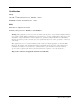
PN 060558-001 Revision B, January 2002 DLP-513 Page 1 of 2 CHECK/ADJUST RF OUTPUT POWER LEVEL Summary: This procedure checks the RF output power level of each channel and describes how to adjust the level if required. Output power level can be measured using the RF OUT connector on the rear panel, or at the MON connector on the front panel. 1. Obtain a spectrum analyzer, RF meter or Stealth meter 2.
PN 060558-001 Revision B, January 2002 DLP-513 Page 2 of 2 LEVEL ADJUST POTENTIOMETER (CHANNEL 3 SHOWN) CH 1 +12 V CPU GND CH 2 CH 3 IPD IPD LVL IPD SD LVL IPD SD LVL 24.0 dBmV RF POWER METER Figure 513-1 RF Output Power Level Check Page 3-36 © 2002, C-COR.
PN 060558-001 Revision B, January 2002 DLP-514 Page 1 of 1 VERIFY ALARMS Summary: This procedure verifies the receiver is capable of communicating with the MICRO Manager through the NMCS. Note: This procedure uses the MICRO Manager Software loaded on a PC to communicate with the receiver through the NMCS. 1. From the MICRO Manager Software, Log On to the system. 2. Use the MICRO Manager Software to address the NMCS and the receiver. 3.
PN 060558-001 Revision B, January 2002 DLP-515 Page 1 of 2 ASSIGN RECEIVER ADDRESS Summary: This procedure assigns a unique identifying address to the receiver that allows proper communication with the MICRO Manager through the NMCS. Note: This procedure uses the MICRO Manager Software loaded on a PC to communicate with the receiver through the NMCS. 1. Using a small flat-blade screwdriver, rotate the ADDRESS switch at the back of the receiver as shown in Figure 515-1, to the desired address.
PN 060558-001 Revision B, January 2002 DLP-515 Page 2 of 2 CH 4 RF OUT NMCS ADDRESS ASSIGN EACH RECEIVER A DIFFERENT ADDRESS B A C 9 8 D 5136-A 7 E 6 F 5 4 0 1 2 3 Figure 515-1 Setting Receiver Address on Rear of Receiver Page 3-39 © 2002, C-COR.
PN 060558-001 Revision B, January 2002 Page 3-40 © 2002, C-COR.
PN 060558-001 Revision B, January 2002 TAP-101 Page 1 of 1 CLEAR COMMUNICATION FAILURE BETWEEN OSWORX MICRO MANAGER SOFTWARE LOADED ON A PC AND RECEIVER Summary: This procedure explains how to correct condition(s) that result in the inability of the MICRO to communicate with the receiver.
PN 060558-001 Revision B, January 2002 Page 3-42 © 2002, C-COR.
World Headquarters 60 Decibel Road State College, PA 16801-7580 USA Tel: 800-233-2267, +1-814-238-2461 Fax: +1-814-238-4065 www.c-cor.net European Office P.O. Box 10.