
Specifications


PN 060558-001
Revision B, January 2002
Page 3-19
© 2002, C-COR.net Corporation
DLP-504
Page 1 of 2
CONNECT ALARMS
Summary: This procedure connects the MAJOR, and MINOR alarm contacts on the receiver to
the corresponding alarm connections on the fuse and alarm panel.
Note: If the fuse and alarm panel has not yet been installed, the alarms can only be
wired at the receiver. It will not be possible to perform initial turn-up and test
procedures.
Warning: To prevent electrical shock, never install electrical equipment in a wet
location or during a lightning storm.
1. Obtain the following tools and equipment:
• Standard hand tools (screwdrivers, pliers, wire cutters, etc.)
• Wire wrap tool
• Cable ties
• Alarm wire (20 or 22 AWG)
2. Place the ESD wrist-band on your wrist and snap the ground wire to the wrist band. Plug
the ground plug into a grounded ESD jack. If an ESD jack is not provided, a small
alligator clip can be attached to the connector on the wrist strap cord. The alligator clip
can then be attached to the ground point on the rack or equipment chassis.
3. Route the cable containing the alarm wires from the receiver to the Fuse and Alarm
Panel location in the rack.
4. Has the fuse and alarm panel been installed?
If YES, route and terminate the alarm wires to the alarm pins on the Fuse and Alarm
Panel (reference vendor manual).
If NO, Coil and leave sufficient wire to reach the alarm pins on the Fuse and Alarm
Panel. Label and secure the wires to the equipment rack.
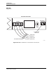
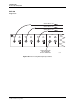
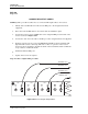
5. Connect the alarm wires to the MAJOR and MINOR alarm screw terminals as shown in
Figure 504-1, at the back of the receiver. The terminals should be wired like an open
switch.
6. Dress the alarm wires at the side of the rack and secure them in position with cable ties.
7. Update office records as required.
Stop! You have completed this procedure.