
Service manual

Chapter 4
Bass Panels
4.1 Disassembly
Both the bass and treble panels are rebuilt in essentially the same way. The elec-
trical connections differ between the panels and this changes the rebuilding sub-
tleties somewhat. However, the basic technique is the same.
The major failure mode for bass panels is either the diaphragm getting brittle
and splitting, or the dust cover splitting and not being repaired. This will allow
the bass panel to fill with dust and dirt which is electrostatically attracted to the
panel assembly just like the diaphragm is attracted to the stators.
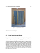
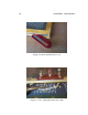
Figure 4.1 shows a set of bass panels removed from the speaker frames. These
panels are typical of the external condition seen in many quads. The left panel
shows the front dust cover where someone has repaired a tear or split with tape.
This is probably the best method for simple repairs although it’s not an elegant
solution, and a better idea is to replace the whole dust cover. The right panel in
figure 4.1 shows the rear dust cover which has torn around the electrical terminal
strip.
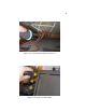
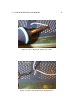
The first step in rebuilding a bass panel is to cut the tape holding the two dust
covers to the stators. The dust covers are taped all around the panel sides. An
effective method is to use a razor blade knife as shown in figure 4.2. The razor
blade should slide easily in the space between the wooden dust cover frame and
the plastic stator panel. The blade is pulled around the parameter for each dust
cover. The front dust cover is then free and can be set aside. The rear dust cover
is still attached to the stator assembly by the electrical connections.
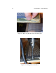
The front and rear stator halves each have an electrical connection riveted to
the bottom center of the panel. The wires from each of these terminals should be
carefully unsoldered. Care should be taken to apply heat to the strip for as short a
time as necessary to remove the wire as the terminal strip is attached to the plastic
stator which can easily melt if too much heat is applied. Figure 4.3 and figure
4.4 show the un-soldering operations. After these two wires are unsoldered, the
23