R CASTILE PELLET INSERT Owner’s Manual Tested and Listed by Installation and Operation Portland Oregon USA O-T L C US OMNI-Test Laboratories, Inc. Models: 810-02901 (MBK) 810-03201 (PMH) CASTINS-CSB CASTINS-CWL CAUTION DO NOT DISCARD THIS MANUAL • Important operating and • Read, understand and follow these instrucmaintenance instructions for safe installations included. tion and operation. WARNING • Leave this manual with party responsible for use and operation.
R Castile Pellet Insert Hearth & Home Technologies welcomes you to our tradition of excellence! In choosing a Quadra-Fire appliance, you have our assurance of commitment to quality, durability, and performance. SAMPLE OF CLEARANCE TO COMBUSTIBLES LABEL LOCATION: On beaded chain behind right access panel. Panel hinges open. This commitment begins with our research of the market, including ‘Voice of the Customer’ contacts, ensuring we make products that will satisfy your needs.
R Castile Pellet Insert Safety Alert Key: • DANGER! Indicates a hazardous situation which, if not avoided will result in death or serious injury. • WARNING! Indicates a hazardous situation which, if not avoided could result in death or serious injury. • CAUTION! Indicates a hazardous situation which, if not avoided, could result in minor or moderate injury. • NOTICE: Indicates practices which may cause damage to the fireplace or to property.
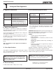
R Castile Pellet Insert 1 Listing and Code Approvals E. BTU & Efficiency Specifications A. Appliance Certification MODEL: Castile Pellet Insert LABORATORY: OMNI Test Laboratories, Inc Particulate Emissions Rating: 0.7 grams/hr REPORT NO. 061-S-42-2 *BTU Output: 8,000 - 30,000 / hr TYPE: Solid Fuel Room Heater/Pellet Fuel Burning Type Insert Heating Capacity: up to 1,500 sq. ft.
R Castile Pellet Insert 2 Getting Started A. Design, Installation & Location Considerations Since pellet exhaust can contain ash, soot or sparks, you must consider the location of: 1. Appliance Location • Windows NOTICE: Check building codes prior to installation. • Installation MUST comply with local, regional, state and national codes and regulations.
R Castile Pellet Insert B. Locating Your Appliance & Chimney D. Negative Pressure Location of the appliance and chimney will affect performance. WARNING! Risk of Asphyxiation! Negative pressure can cause spillage of combustion fumes and soot. • • Install through the warm airspace enclosed by the building envelope. This helps to produce more draft, especially during lighting and die-down of the fire. Penetrate the highest part of the roof. This minimizes the effects of wind loading.
R Castile Pellet Insert E. Fire Safety F. Tools And Supplies Needed To provide reasonable fire safety, the following should be given serious consideration: • Install at least one smoke detector on each floor of your home. • Locate smoke detector away from the heating appliance and close to the sleeping areas. • Follow the smoke detector manufacturer’s placement and installation instructions and maintain regularly. • Conveniently locate a Class A fire extinguisher to contend with small fires.
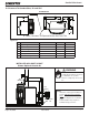
R Castile Pellet Insert 3 Dimensions and Clearances A. Appliance Dimensions 28-1/16 in. 43-1/2 in. (713mm) (1105mm) 23-7/16 in. (595mm) 42-1/2 in. (1080mm) 8 in. (203mm) 11-1/16 in. (281mm) 30-3/8 in. (772mm) 30 in. (762mm) 32-5/16 in. (821mm) Figure 8.2- Front View Figure 8.1 - Top View Height Panel Size Width inch mm inch mm Small Cast 30 762 Large Cast 34 864 48 1219 Small Econo 30 762 40 1016 10-3/16 in. 13-1/16 in. (259mm) (332mm) 42-1/2 1078 24-3/16 in.
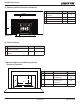
R Castile Pellet Insert B. Clearance To Combustibles, UL and ULC AS A BUILT-IN A C D B B C E 0” (0mm) Clearance To Exposed Section And Face Trim Figure 9.1 Inches Millimeters A Top of Hopper Top or Rear Vent 0 0 B Side of Outside Skin Top or Rear Vent 0 0 C Back of Hopper Top Vent 2.5 64 Rear Vent 0 0 D Vent Pipe to Combustible Top or Rear Vent 3.0 76 E Front Panel Edge Top or Rear Vent 0 0 INSTALLED AS A BUILT-IN UNIT Shown Optional Outside Air WARNING Fire Risk.
R Castile Pellet Insert C. Masonry and Zero Clearance Fireplaces Inches Millimeters MANTEL SIDE WALL B C A Insert side to combustible side wall 0 0 B Insert top to mantel 12 305 C Insert top to face trim 0 0 D Insert side to face trim 0 0 D A E F Figure 10.1 D. Floor Protection Inches Millimeters E Floor protection hearth extension from door opening 6 152 F Floor protection to the side of door opening 6 152 E.
R Castile Pellet Insert F. Removing Metal Floor of Factory-Built Firebox • • • The firebrick (refractory), glass doors, screen rails, screen mesh and log grates can be removed from a factory-built firebox in order to gain minimum insert opening requirements. Any smoke shelves, shields and baffles may be removed from a factory-built firebox if attached with mechanical fasteners.
R Castile Pellet Insert G. Prefabricated Metal Chimney H. Altering the Factory-Built Fireplace The chimney can be new or existing, masonry or prefabricated and must meet the following minimum requirements: • • Must be minimum 6 inch (152mm) inside diameter of high temperature chimney listed to UL 103 HT (2100oF) or ULC-S628. The fireplace must not be altered, except for the exceptions listed below. Do not removal the bricks and mortar from the existing fireplace.
R Castile Pellet Insert 4 Vent Information B. Venting Termination Requirements A. Chimney and Exhaust Connection CAUTION 1. Chimney & Connector: Use 3 or 4 inch (76-102mm) diameter type "L" or "PL" venting system. It can be vented vertically or horizontally. 2. Mobile Home: Approved for all Listed pellet vent. If using the 3 inch (76mm) vertical Top Vent Adapter Kit or the 3 to 6 inch (76-152mm) Top Vent Offset Adapter, use Listed double wall flue connector.
R Castile Pellet Insert WARNING C. Equivalent Feet of Pipe The table below can help you calculate the equivalent feet of pipe which is a method used to determine pellet vent size. Figure 14.1. Improper installation, adjustment, alteration, service or maintenance can cause injury or property damage. Refer to the owner’s information manual provided with this appliance. For assistance or additional information consult a qualified installer, service agency or your dealer.
R Castile Pellet Insert 5 Venting Systems A. Full Reline With Outside Air - Horizontal WARNING Fire Risk. Inspection of Chimney: • Masonry chimney must be in good condition. • Meets minimum standard of NFPA 211 • Factory-built chimney must be a minimum 6 inch (152mm) UL103 HT.
R Castile Pellet Insert B. Full Reline With Outside Air - Vertical NOTE: Check clearances carefully for this type of installation to ensure adequate room for outside air venting. NOTE: In Canada only a full reline is allowed per ULC S628, ORD ULC C1482-M1990. 305mm min. above 305mm min. below NOTE; Use metal plate around exhaust vent pipe and seal all edges with non-flammable insulation such as fiberglass, mineral wool or ceramic.
R Castile Pellet Insert 6 Mobile Home A. Mobile Home Installation You must use a Quadra-Fire Outside Air Kit for installation in a mobile home. 1. An outside air inlet must be provided for the combustion air and must remain clear of leaves, debris, ice and/or snow. It must be unrestricted while the appliance is in use to prevent room air starvation which causes smoke spillage. Smoke spillage can also set off smoke alarms. 2. The combustion air duct system must be made of metal.
R Castile Pellet Insert 7 Appliance Set-Up A. Reversible Top or Rear Flue Adapter B. Leveling System Top Vent Installation The back legs are adjustable to allow for customized fit into zero clearance boxes. 1. Release ammo can latches on each side. Figure 18.1. 2. Place the reversible adapter in the correct position for your installation. 3. Make sure BOTH latches are in position before securing them. Rear Vent Installation 1. Remove the 90o adapter and installation screws from the packaging. 1.
R Castile Pellet Insert C. Outside Air Kit Instructions D. Zero Clearance Trim Support Instructions Parts Included in Kit: 1 piece of 2 inch x 3 ft. flex hose, 2 hose clamps, 1 collar assembly, 1 termination cap assembly, 1 air intake channel, 1 trim ring, fasteners. NOTE: Discard air intake channel, it is not used on this appliance. NOTE: Only for use on small size panels. Tools Needed: Phillips head screwdriver; wire cutters; hole saw or jig saw. 1. Attach collar assembly to appliance. Figure 19.1.
R Castile Pellet Insert D. Zero Clearance Trim Support (Cont’d) Cast Trim Footer 1. Remove contents from box and lay on protective surface to avoid scratching the paint. 2. Lay zero clearance front and sides face down. Bend the tab down toward the inside. 3. The side pieces are shipped flat. It is much easier to manually flex the sides into a bowed position before installing. 4. Lay 1 cast ring face up, which will become the bottom ring when installed. Attach the 2 sides FIRST and then the front piece.
R Castile Pellet Insert E. Panel Set And Cast Trim Set F. Panel & Trim Set, Econo Included in Panel Kit: (2) side panels, left and right; (1) panel top; (1) fastener package. Included in Panel & Trim Kit: (2) corner brackets and set screws; (1) trim set, 3 piece; (2) side panels; (1) top panel; (4) screws; Included in Cast Trim Kit: (2) cast trim legs, left and right; (1) cast trim header; (2) cast trim footers, left and right; (1) fastener package.
R Castile Pellet Insert G. Optional Log Set Placement Instructions CAUTION Logs are FRAGILE. Use extreme care when handling or cleaning logs. Four Piece Log Set Installation 1. Open the hinged cast face and open the glass door assembly. 2. Positioning the logs. Place the right rear log as shown. There is a notch in the bottom of the log for clearance for the thermocouple and thermocouple cover (ceramic protection tube). Figure 22.1 Figure 22.
R Castile Pellet Insert H. Thermostat Installation 1. 2. A 12 volt AC thermostat is required to operate this pellet appliance. You may use the included wall mount thermostat or purchase an optional programmable thermostat or remote control. The included thermostat is equipped with an adjustable heat anticipator. The current rating is .05 amps. The anticipator needs to be adjusted to the lowest setting available. CAUTION Shock hazard. • Do NOT remove grounding prong from plug.
R Castile Pellet Insert 8 Operating Instructions A. Fuel Size, Material and Storage 2. Shelled Field Corn (Cont’d) 1. Wood Pellets Fuel pellets are made from sawdust or wood by-products. If the source material is hardwood, they can have a higher mineral content, creating more ash. Fuels containing bark will also have higher ash content.
R Castile Pellet Insert C. Before Your First Fire B. General Operating Information 1. Thermostat Calls For Heat 1. First, make sure your appliance has been properly installed and that all safety requirements have been met. Pay particular attention to the fire protection, venting and thermostat installation instructions. The appliance is like most modern furnaces; when the thermostat calls for heat, your appliance will automatically light and deliver heat.
R Castile Pellet Insert F. Feed Rate Adjustment The fuel adjustment control rod is factory set, and should be adequate for most fuels. Control Box Red Call Light The set screw is located at the bottom of the hopper and set loose at the factory so the fuel adjustment control rod will slide by only loosening the wing nut. Do not re-tighten bottom set screw. Fuse Power Cord Outlet t e gh Li u Bl However, if the flame height is too high or too low, you will need to adjust the feed rate.
R Castile Pellet Insert H. Frequently Asked Questions ISSUES SOLUTIONS 1. Metallic noise. 1. Noise is caused by metal expanding and contracting as it heats up and cools down, similar to the sound produced by a furnace or heating duct. This noise does not affect the operation or longevity of your appliance. 2. Ash buildup on glass. 2. This is normal. Clean the glass. 3. Glass has turned dirty. 3. Excessive build up of ash.
R Castile Pellet Insert 9 With proper installation, operation, and maintenance your appliance will provide years of trouble-free service. If you do experience a problem, this troubleshooting guide will assist a qualified service person in the diagnosis of a problem and the corrective action to be taken. This troubleshooting guide can only be used by a qualified service technician. Troubleshooting Possible Cause Symptom Plug in appliance - No response. Call light on. No fire. No fuel in firepot.
R Castile Pellet Insert Symptom Possible Cause Corrective Action Slow or smoky start-up (Cont’d) Dirty exhaust and/or venting system. Check for ash build up in appliance, including behind rear panels, firebox, heat exchanger, exhaust blower and venting. Feed system fails to start. Out of fuel. Check hopper, fill with fuel. #2 snap disc may be defective. Replace snap disc. Firebox door must be closed securely. Vacuum switch not closing. No vacuum.
R Castile Pellet Insert Symptom Convection blower fails to start. Exhaust blower fails to start or does not shut off. Large, lazy flame, orange color. Black ash on glass. Possible Cause No call light. Defective control box. #1 snap disc defective. Replace snap disc. Blower not plugged in. Check that blower is plugged into wire harness. Blower is defective. Replace blower. Control box is defective. Replace control box. Blower not plugged in. Check that blower is plugged into wire harness.
R Castile Pellet Insert 10 Maintaining & Servicing Your Appliance C. General Maintenance & Cleaning A. Proper Shutdown Procedure 1. Types of Fuel Depending on the type of fuel you are burning will dictate how often you have to clean your firepot. CAUTION Shock and Smoke Hazard • Turn down thermostat, let appliance completely cool and exhaust blower must be off. Now you can unplug appliance before servicing. • Smoke spillage into room can occur if appliance is not cool before unplugging.
R Castile Pellet Insert 3. Cleaning Firepot with Cleaning Rod & Firepot Scraper 2. Remove Cast Sides for Cleaning & Maintenance a. Loosen screw on top right corner directly under the cast top, but do not remove. Figure 32.1. • • b. With thumb, press upward on the frame to relieve the pressure on the cast side. Figure 32.2. Frequency: Daily or more often as needed By: Homeowner a. The appliance must be in complete shutdown and cool and the exhaust blower off.
R Castile Pellet Insert 7. Disposal of Ashes 4. Ash Removal from Firebox (Cont’d) e. The 2 cleaning slide plates must be fully closed when cleaning is complete. See Disposal of Ashes. • • Ashes should be placed in a metal container with a tight-fitting lid. The closed container of ashes should be placed on a non-combustible floor or on the ground, well away from all combustible materials, pending final disposal. 5.
R Castile Pellet Insert 10. Cleaning the Hopper • • CAUTION Frequency: Monthly or after burning 1 ton of fuel By: Homeowner Handle glass assembly with care. After burning approximately 1 ton of fuel you will need to clean the hopper to prevent sawdust build-up. When cleaning glass: • Avoid striking, scratching or slamming glass. • Do NOT clean glass when hot. A combination of sawdust and pellets on the auger reduces the amount of fuel supply to the firepot.
R Castile Pellet Insert 16. Door Gasket Inspection D. High Ash Fuel Content Maintenance • • • Frequency: Monthly or after burning 1 ton of fuel By: Homeowner To inspect the door rope (gasket), open the door and see that the door rope extends approximately 1/8 to 3/16 inch (3 to 9.5mm) from the door rope channel. It should show signs of compaction all the way around the door where the rope contacts the face of the insert. 17. Preparing Firebox for Non-Burn Season • • Frequency: Yearly By: Homeowner a.
R Castile Pellet Insert E. Igniter Replacement F. Glass Replacement WARNING • Glass is 5mm thick high temperature heatresistant ceramic glass. • DO NOT REPLACE with any other material. • Alternate material may shatter and cause injury Igniter Bracket Thumb Screw a. Open hinged cast face and lift door assembly off from the insert and lay on a flat surface face down. Igniter Figure 36.1 a. Shut down the appliance by turning down the thermostat and let the appliance completely cool down.
R Castile Pellet Insert Re-installing Baffle & Brick Set G. Baffle & Brick Set Removal 1. Follow proper shutdown procedures on Page 31. The top baffle has a hook on the bottom left side that rests on the top lip of the cast brick. There is a tab on the bottom right side that hooks into the side bracket. Remove the top baffle by first pulling the baffle forward until back edge drops down. Then slide baffle back until the front edge clears the shelf that it had been resting on. Figure 37.1. 3.
R Castile Pellet Insert Re-installing Baffle & Brick Set (Cont’d) Lift brick, pull forward at an angle and drop down into notches Hook on left side Tab on right side Figure 38.4 Figure 38.1 Figure 38.5 Figure 38.2 Figure 38.
R Castile Pellet Insert 11 Reference Materials A. Component Function 1. Control Box E a. The control box is located on lower right side of appliance, behind cast side on top of the junction box. b. There is a light located inside of the control box. The internal light will turn green when the appliance has reached a temperature of 200οF (93°C) in the firepot. and will turn red when it reaches 600oF (315°C). c. There is also an internal blue light located in the upper left corner of the control box.
R Castile Pellet Insert 16. Snap Disc #1 (Convection Blower) 110°F 19. Vacuum Switch Snap disc #1 is located behind the right cast side of the firebox above the red call light. There are 2 purple wires connected to it. This snap disc turns the convection blower on and off as needed. Power is always present at snap disc #1. The vacuum switch is located at the back of the appliance. This switch turns the feed system on when vacuum is present in the firebox.
R Castile Pellet Insert B. Component Locations 10 Heat Exchanger Tubes Feed Motor CLEANING RODS Exhaust Blower Figure 41.2 - Cleaning Rods & Heat Exchanger Tubes Convection Blower Figure 41.1 - Blowers & Feed Motor Control Box Red Call Light Fuse Power Cord Outlet t B e lu gh Li t be rL h ig Am n/ ed Heat Output Switch /G e re R Thermostat Block Reset Button Junction Box Figure 41.
R Castile Pellet Insert C. Exploded Drawing 33 1 32 2 30 31 29 28 27 3 26 25 4 24 23 5 22 6 21 7 8 19 20 9 18 17 16 15 14 10 12 Figure 42.
R Castile Pellet Insert D. Service Parts and Accessories HOW TO ORDER IMPORTANT: THIS IS DATED INFORMATION To order the entire assembly, order the top line part number only. To order an individual part from an assembly, order the part(s) listed in the indented portion. When requesting service or replacement parts for your appliance please provide model number and serial number. All parts listed may be orderd from an authorized dealer.
R Castile Pellet Insert HOW TO ORDER Item To order the entire assembly, order the top line part number only. To order an individual part from an assembly, order the part(s) listed in the indented portion. Description 18 Part Number Gasket, Tadpole, 3/8 Qty: 10 Ft., Field cut to size 842-5130 Y Glass Assembly 17-1/in. W x 11-5/8 in. H 7001-038 Y Hinge, Female 450-2910 Retainer, Rope 7001-192 Tape, Door Corner 17 Comments Stocked at Depot Qty: 1 Ft.
R Castile Pellet Insert To order the entire assembly, order the top line part number only. To order an individual part from an assembly, order the part(s) listed in the indented portion.
R Castile Pellet Insert HOW TO ORDER Item To order the entire assembly, order the top line part number only. To order an individual part from an assembly, order the part(s) listed in the indented portion.
R Castile Pellet Insert HOW TO ORDER Item To order the entire assembly, order the top line part number only. To order an individual part from an assembly, order the part(s) listed in the indented portion.
R Castile Pellet Insert E.
R Castile Pellet Insert E.
R Castile Pellet Insert F.
R Castile Pellet Insert August 20, 2009 250-7251G Page 51
R CONTACT INFORMATION: Hearth & Home Technologies 1445 North Highway Colville, WA 99114 Division of HNI INDUSTRIES Please contact your Quadra-Fire dealer with any questions or concerns. For the number of your nearest Quadra-Fire dealer please visit our web site at www.quadrafire.com NOTICE • Leave this manual with party responsible for use and operation.